Spinning progressive forming device

A technology of progressive forming and pressing rod, applied in forming tools, metal processing equipment, manufacturing tools, etc., can solve the problems of sheet metal springback, low processing efficiency, instability, etc., to reduce the springback effect, improve the forming efficiency, The effect of increasing the forming limit

Active Publication Date: 2021-09-17
SHANGHAI OCEAN UNIV
View PDF10 Cites 0 Cited by
  • Summary
  • Abstract
  • Description
  • Claims
  • Application Information

AI Technical Summary

Problems solved by technology

[0005] Aiming at the low processing efficiency of the single-point incremental forming device in the prior art and the problems of springback, instability and depression of the metal sheet after processing, the purpose of the present invention is to A spinning progressive forming device is provided

Method used


Image

  • Spinning progressive forming device
  • Spinning progressive forming device
  • Spinning progressive forming device

Examples


Embodiment 1

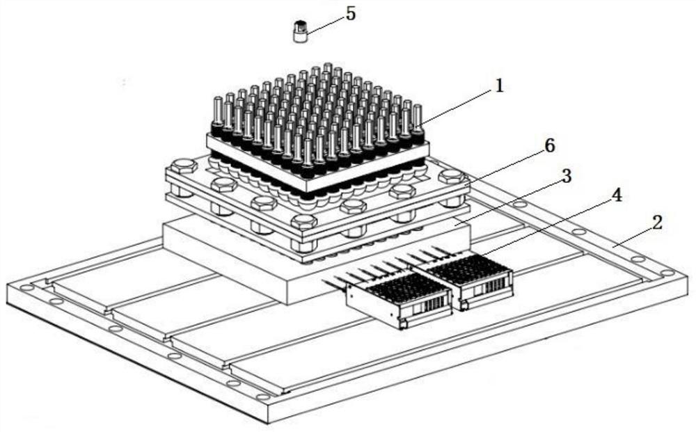
[0039] A spinning incremental forming device, such as figure 1 As shown, it includes a spinning assembly 1 , a workbench 2 , a thermal elastic assembly 3 and a pressing assembly 6 .

[0040] In this embodiment, the workbench 2 is configured as a flat plate made of cast iron. Since the cast iron has the ability to absorb machine vibration, the precision of forming the metal sheet can be improved.

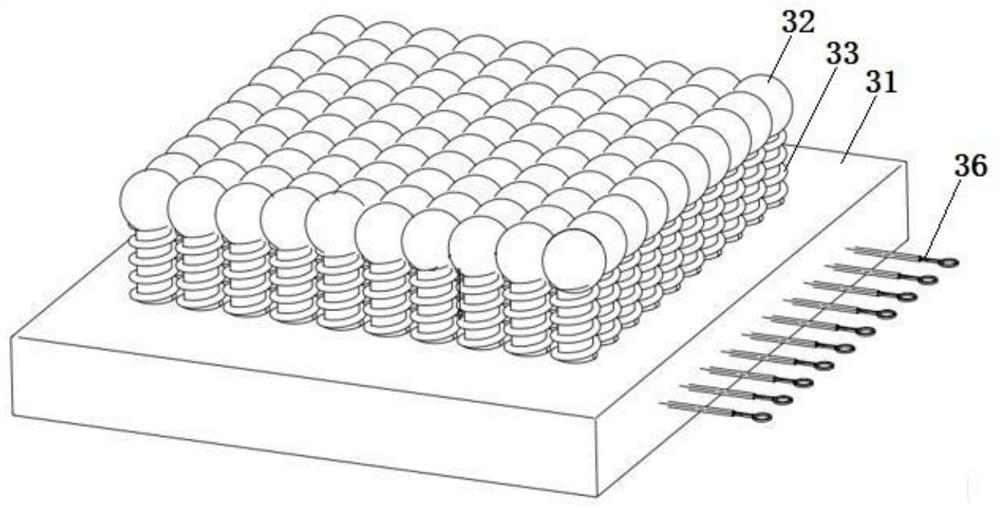
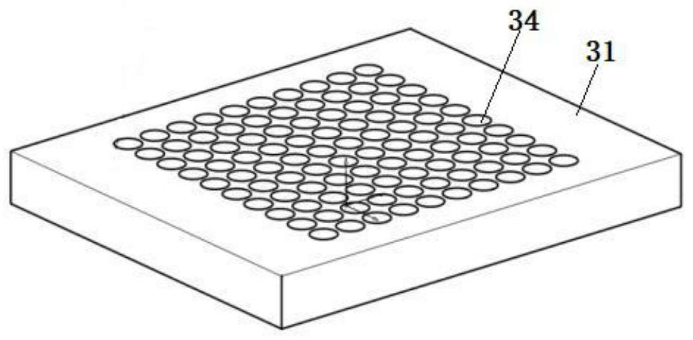
[0041] In this example, if Figure 2-4 As shown, the thermal elastic assembly 3 includes a thermal elastic plate 31 and a plurality of heating ball heads 32 . The thermoelastic plate 31 is a flat plate, which is placed or fixed on the workbench 2. The central part of the thermoelastic plate 31 is provided with a thermoelastic area, and the above-mentioned plurality of heating ball heads 32 are evenly distributed in the thermoelastic area. Specifically, Preferably, a plurality of elastic reset members 33 are arranged in an evenly distributed manner on the thermal elastic region, and...

Embodiment 2

[0050] It differs from Embodiment 1 in that: in this embodiment, the thermoelastic assembly 3 also includes a hollow rigid guide post 37, such as Figure 4 As shown, and each coil spring is equipped with a rigid guide column 37, the rigid guide column 37 passes through the coil spring, that is, the rigid guide column 37 is also arranged in the placement hole 34, and the top end of the rigid guide column 37 is also fixed It is connected to the heating ball head 32, so as to guide and restrict the coil spring during telescopic movement, and prevent the coil spring from being affected by the elastic effect due to deviation or lodging. Correspondingly, the above-mentioned wire 36 passes through the hollow structure of the rigid guide post 37 .

Embodiment 3

[0052] The difference between it and Embodiment 1 is: in this embodiment, if Figure 5 As shown, the pressing assembly 6 is set to further include a support plate 63, the support plate 63 is annular, the support plate 63 is placed on the top surface of the thermal elastic plate 3 and the frame of the support plate 63 is arranged around the thermal elastic area, and at the same time, the support plate 63 is located Below the two pressing plates 61 , so as to provide support for the bolts 62 through the frame of the support plate 63 .

[0053] Such an arrangement enables the overall stability to be improved by the support plate 63 .

[0054] In addition, threaded holes can also be provided on the frame of the support plate 63 so that the studs of the bolts 62 can be screwed therein, so that the press assembly 6 is connected and fixed as a whole.


PUM


Abstract

The invention discloses a spinning progressive forming device, and belongs to the technical field of plate forming. The spinning progressive forming device comprises a workbench, a thermal elastic assembly, a pressing assembly and a spinning assembly, wherein the thermal elastic assembly, the pressing assembly and the spinning assembly are stacked on the workbench from bottom to top; the thermal elastic assembly comprises a thermal elastic plate arranged on the workbench and a plurality of heating balls arranged in a thermal elastic area on the thermal elastic plate, and the heating balls are connected to the top face of the thermal elastic plate through elastic reset parts; the pressing assembly comprises two pressing plates which are oppositely arranged and detachably connected, and hollowed-out holes are formed in the opposite positions of the pressing plates correspondingly so that a to-be-pressed plate can be clamped to the edges of the hollowed-out holes; the spinning assembly comprises a spinning plate, a plurality of spinning rods in threaded connection in a spinning area on the spinning plate, and spinning heads arranged at the lower ends of the spinning rods; and the thermoelastic area and the spinning area are opposite to the hollowed-out holes. According to the spinning progressive forming device, the forming of the plate is efficient, the flexibility is high, and the anti-rebound performance is high.

Description

technical field [0001] The invention relates to the technical field of plate forming, in particular to a spinning progressive forming device. Background technique [0002] With the development of science and technology, single-point incremental forming technology has been widely used in the processing of small batches of metal sheets with complex shapes, such as in aerospace, automobiles, ships and other fields. [0003] However, many single-point forming devices on the market have low processing efficiency, and problems such as springback, instability, and dents of the metal sheet after processing. [0004] Therefore, based on the numerous single-point forming devices in the existing market, it is urgent to develop a spinning single-point progressive forming device with high efficiency, high flexibility and high rebound resistance. Contents of the invention [0005] In view of the low processing efficiency of the single-point incremental forming device in the prior art a...

Claims


Application Information

Patent Timeline
Patent Type & Authority Applications(China)
IPC IPC(8): B21D31/00B21D22/14B21D37/16
CPCB21D31/005B21D22/14B21D37/16
Inventor 王斌朱峰倪正峰邹高武吴海军张福曦
Owner SHANGHAI OCEAN UNIV
Why Eureka
Try Eureka