Downward pressing type sealing device

A sealing device and sealing film technology, used in measuring devices, fluid tightness testing, transportation and packaging, etc., can solve the problems of unsatisfactory sealing effect, cumbersome operation, time-consuming and labor-intensive, etc., to improve the degree of automation and efficiency, Conducive to the effect of efficient execution

Active Publication Date: 2021-09-17
SUZHOU RS TECH
View PDF15 Cites 0 Cited by
  • Summary
  • Abstract
  • Description
  • Claims
  • Application Information

AI Technical Summary

Problems solved by technology

[0003]The common sealing film attachment is to pre-cut the sealing film to the required length, and then transfer it to the opening of the workpiece to be sealed by a robot or manually , and then press the sealing pressure head onto the sealing film. After the inspection is completed, the used sealing film will be removed and recovered by a robot or manually. The above-mentioned traditional sealing methods are cumbersome to operate, time-consuming and labor-intensive, and the sealing effect is not ideal. And other issues

Method used


Image

  • Downward pressing type sealing device
  • Downward pressing type sealing device
  • Downward pressing type sealing device

Examples


Embodiment 1

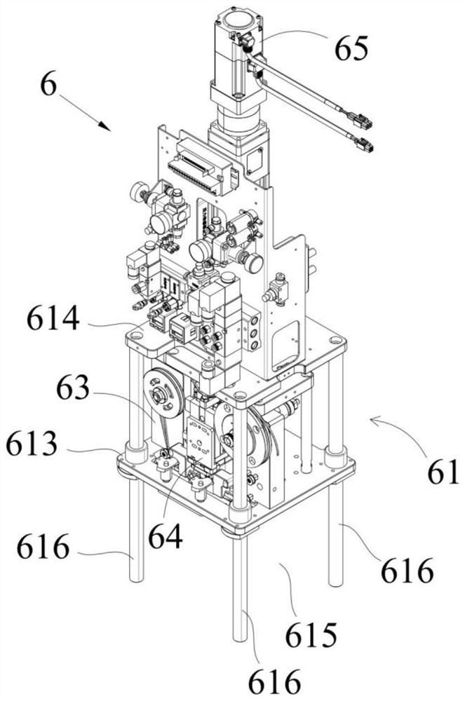
[0047] Figure 1 ~ Figure 4 Embodiment 1 of the present invention is shown, combined with Figure 1 ~ Figure 4 From the illustration, it can be seen that the push-down sealing device 6 includes:

[0048] The installation bracket 61, the installation bracket 61 includes at least three non-collinear lifting guide columns 616, a downward pressure mounting plate 613 that is movably socketed on the lifting guide columns 616 and fixed on the lifting guide columns 616 The fixed installation plate 614, the press-down installation plate 613 is located below the fixed installation plate 614 and spaced apart from the fixed installation plate 614 to form an installation space between the two, the press-down installation plate 613 A workpiece positioning space 615 is formed directly below;

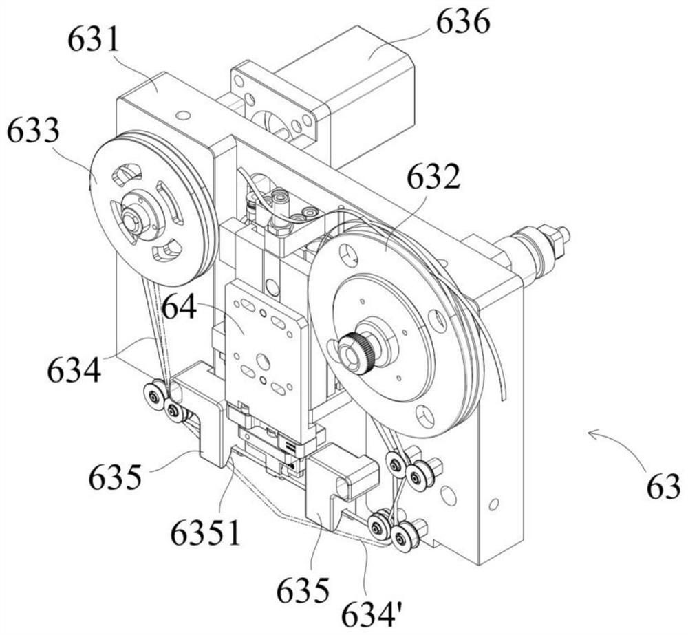
[0049] The bonding module 63 installed on the press-down mounting plate 613 and located in the installation space, wherein a press-down sealing mechanism 64 is fixedly installed; and

[0050] The li...

Embodiment 2

[0068] Figure 3 ~ Figure 6 Also shows embodiment 2 of the present invention, the difference between embodiment 2 and embodiment 1 is:

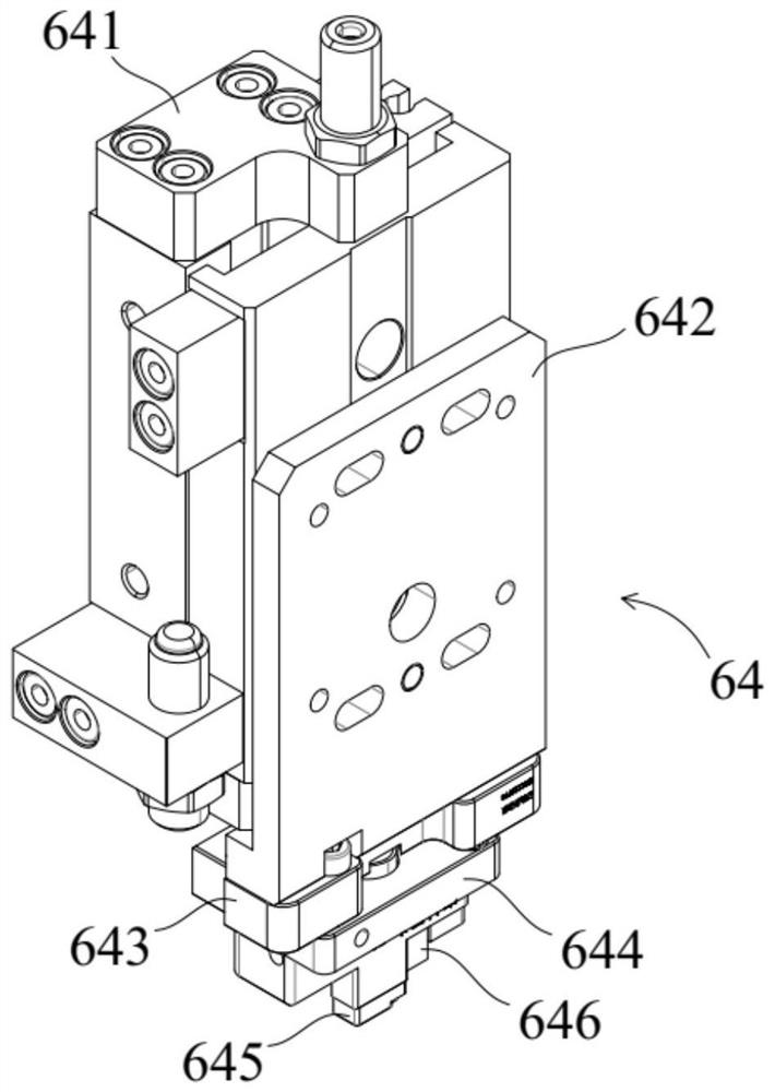
[0069] The sealing head assembly includes:

[0070] The mounting base 644 slidably connected to the bottom of the indenter mounting plate 643 has a mounting portion 6442 hanging downwards from the bottom thereof, and an indenter accommodating groove 6445 with an open bottom is formed in the mounting portion 6442; and

[0071] The sealing pressure head 645 fitted in the pressure head accommodation groove 6445;

[0072] Wherein, a replacement opening 6446 communicating with the outside is opened on the side of the pressure head accommodation groove 6445, and the sealing pressure head 645 enters and exits the pressure head accommodation groove 6445 through the replacement opening 6446 to complete the sealing pressure head 645 installation and replacement.

[0073] refer to image 3 At least two buffer slots 6441 are opened in the installatio...


PUM


Abstract

The invention discloses a downward pressing type sealing device. The device comprises an installation support which comprises at least three lifting guide columns arranged in a non-collinear mode, a downward pressing installation plate movably connected to the lifting guide columns in a sleeving mode and a fixed installation plate fixedly connected to the lifting guide columns. The downward pressing installation plate is located below the fixed installation plate, the downward pressing installation plate and the fixed installation plate are arranged in a spaced mode to form a mounting space located between the downward pressing installation plate and the fixed installation plate, and a workpiece positioning space is formed under the downward pressing installation plate; a laminating module is installed on the downward pressing installation plate and located in the installation space, and a downward pressing type sealing mechanism is fixedly mounted in the laminating module; the lifting driver is installed on the fixed installation plate, and the power output end of the lifting driver is in transmission connection with the laminating module. According to the invention, the sealing film can be continuously released and the pressing sealing operation can be carried out on the sealing film transmission path, and the used sealing film can be continuously and automatically recovered.

Description

technical field [0001] The invention relates to the field of non-standard automation equipment, in particular to a push-down sealing device. Background technique [0002] In the field of non-standard automation equipment, it is well known that sealing devices of different structures are used to seal the opening of the workpiece to be sealed so as to facilitate the smooth progress of the subsequent sealing test. In the process of researching and realizing the sealing of the workpiece opening, the researchers found that the sealing device in the prior art has at least the following problems: [0003] The common sealing film attachment is to pre-cut the sealing film to the required length, and then transfer it to the opening of the workpiece to be sealed by a robot or manually, and then press the sealing head down on the sealing film. After the inspection is completed, the used sealing film is removed and recovered by a robot or manually. The above-mentioned traditional sealin...

Claims


Application Information

Patent Timeline
Patent Type & Authority Applications(China)
IPC IPC(8): B65H37/00G01M3/00
CPCB65H37/00G01M3/00
Inventor 吴华徐振光马运曦刘育林
Owner SUZHOU RS TECH
Why Eureka
Try Eureka