Light irradiation unit and light irradiation device
A light irradiation device and light irradiation technology are applied in the directions of electric heating devices, ohmic resistance heating devices, electrical components, etc., which can solve the problems of reduced illuminance and achieve the effect of high illuminance uniformity.
- Summary
- Abstract
- Description
- Claims
- Application Information
AI Technical Summary
Problems solved by technology
Method used
Image

Examples
no. 1 approach >
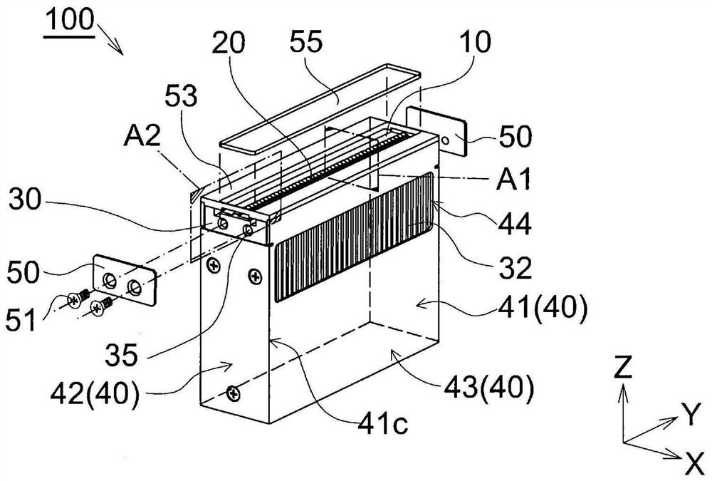
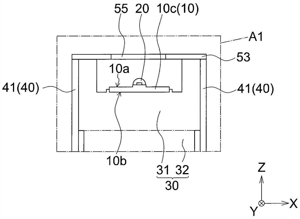
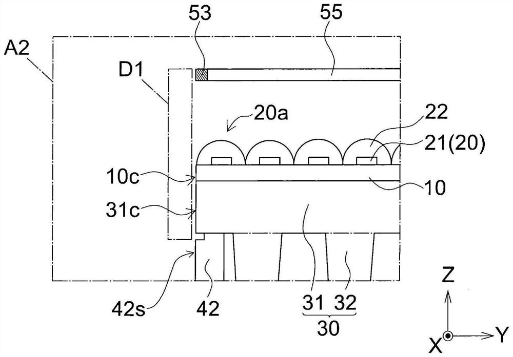
[0070] One embodiment of the light irradiation unit will be described with reference to the drawings. In addition, each drawing disclosed in this specification is a figure which shows schematically only. That is, the dimensional ratios in the drawings do not necessarily match the actual dimensional ratios, and the dimensional ratios do not necessarily match between the drawings.
[0071] Hereinafter, description will be made with reference to the XYZ coordinate system as appropriate. In addition, in this specification, when expressing a direction, when distinguishing the orientation of positive and negative, it describes with the sign of plus and minus so that "+X direction" and "-X direction" are added. In addition, when expressing a direction by distinguishing positive and negative orientation, it describes only as "X direction". That is, in this specification, when only "X direction" is described, both "+X direction" and "-X direction" are included. The same applies to t...
no. 2 approach >
[0098] The light irradiation unit of the second embodiment will be described. Matters other than those described below can be implemented in the same manner as in the first embodiment. The same applies to the third and subsequent embodiments. Figure 6 is a perspective view of the light irradiation unit 200 . Figure 7 will be Figure 6 An enlarged view of the section of the A3 region parallel to the YZ plane.
[0099] In the light irradiation unit 200 , the second side surface 46 covers the entire heat dissipation member 30 , that is, both the main body 31 (end surface 31 c ) and the fins 32 . The area D2 is an area where the protective member 60 is fixed. The position in the Y-axis direction of the end surface 10 c of the substrate 10 coincides with the position in the Y-axis direction of the end surface 31 c of the main body 31 . When the light irradiation unit 200 is connected in the Y-axis direction, the end surface 10c of the substrate 10 is located on the inner sid...
no. 3 approach >
[0101] Figure 8 It is an enlarged view in which only the connecting portion of two light irradiation units (300a, 300b) in the light irradiation device 300 of the third embodiment is viewed from the +Z side to the -Z side. However, for convenience of explanation, the optical member 55 and the lens 22 provided on each light source 20 are not shown.
[0102] The light irradiation device 300 is arranged so that the end faces 10c of the light irradiation units (300a, 300b) of the same specification are in contact with each other. The LED chips (21a to 21c, 21d to 21f) in the light irradiation unit are arranged at a constant interval of a (mm) in the Y-axis direction. The distance in the Y-axis direction between the end surface 10c and the center of the LED chip (21c, 21d) closest to the end surface 10c among the LED chips (21a-21f) is b (mm). Then, the relationship of b=a / 2 is satisfied.
[0103] In the light irradiation device 300 in which the light irradiation units (300a, 3...
PUM
 Abstract
Description
Claims
Application Information
 - R&D
- Intellectual Property
- Life Sciences
- Materials
- Tech Scout
- Unparalleled Data Quality
- Higher Quality Content
- 60% Fewer Hallucinations
Browse by: Latest US Patents, China's latest patents, Technical Efficacy Thesaurus, Application Domain, Technology Topic, Popular Technical Reports.
© 2025 PatSnap. All rights reserved.Legal|Privacy policy|Modern Slavery Act Transparency Statement|Sitemap|About US| Contact US: help@patsnap.com