Energy-saving and environment-friendly shower water sediment discharging device for livestock farm

An energy-saving and environmentally friendly discharge device technology, which is applied to the feeding/discharging device of the settling tank, sedimentation separation, separation method, etc., can solve problems such as low work efficiency, troublesome sediment recovery, and more time and energy. Achieve the effects of improving efficiency, complete discharge, and simple and convenient operation

Active Publication Date: 2021-09-21
山东毅海农牧发展有限公司
View PDF9 Cites 0 Cited by
  • Summary
  • Abstract
  • Description
  • Claims
  • Application Information

AI Technical Summary

Problems solved by technology

[0004] In order to overcome the disadvantages that the current device is more troublesome to recover the sediment, it takes more time and energy, and the work efficiency is lower. The technical problem is: to provide an energy-saving and environment-friendly shower water precipitation for farms that is relatively simple and convenient to collect sediment. waste discharge device

Method used


Image

  • Energy-saving and environment-friendly shower water sediment discharging device for livestock farm
  • Energy-saving and environment-friendly shower water sediment discharging device for livestock farm
  • Energy-saving and environment-friendly shower water sediment discharging device for livestock farm

Examples


Embodiment 1

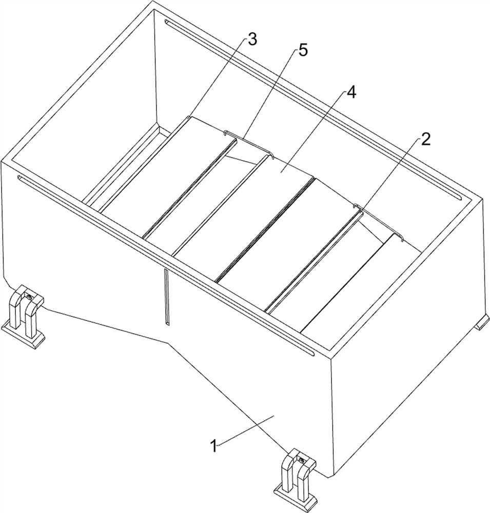
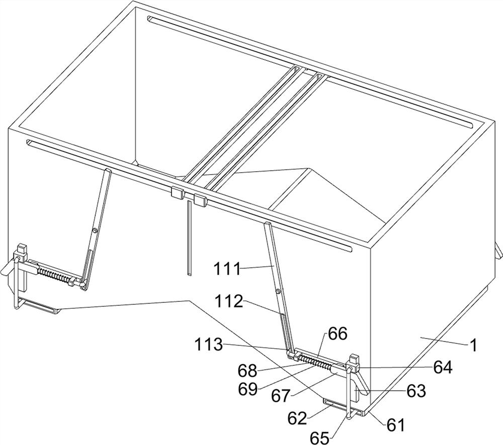
[0028] An energy-saving and environment-friendly shower water sediment discharge device for farms, such as Figure 1-3 As shown, it includes a frame body 1, a V-shaped plate 2, a slant plate 3, a shield cover plate 4, a concave connecting rod 5 and a discharge assembly 6. The inner lower side of the frame body 1 is provided with a V-shaped plate 2, and the frame body 1 The left and right sides of the inner lower part of the slant plate 3 are all provided with a slant plate 3, and the upper side of the slant plate 3 and the left and right sides of the V-shaped plate 2 are slidingly provided with a shield cover 4, and the shield cover 4 on the left and right sides is located between the front and rear sides. A concave connecting rod 5 is connected between them, and a discharge assembly 6 is arranged on the frame body 1 .

[0029] When the shower water sediment needs to be discharged, the shower water is discharged into the frame body 1, and then the sediment enters the bottom of...

Embodiment 2

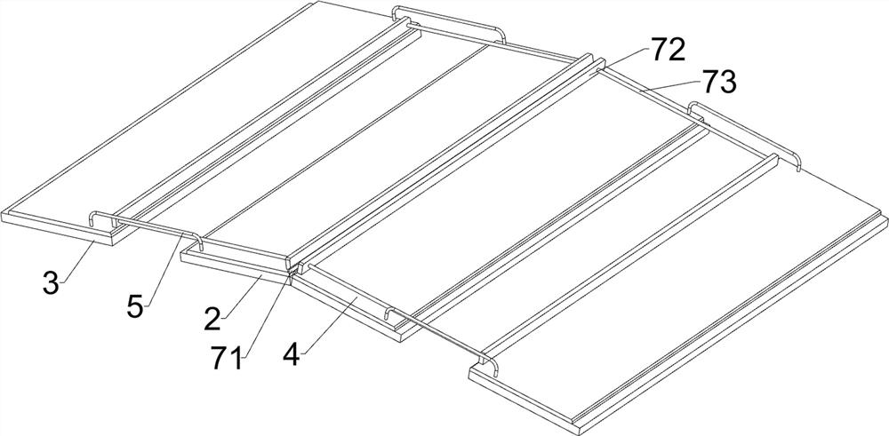
[0033] On the basis of Example 1, such as figure 1 , image 3 , Figure 4 , Figure 5 , Figure 6 and Figure 7 As shown, it also includes a scraper assembly 7, the scraper assembly 7 includes a stopper 71, a scraper 72 and a straight connecting rod 73, the upper side of the middle shield cover plate 4 is provided with a stopper 71, and the upper side of the shield cover plate 4 The upper side is slidingly provided with a scraper 72, the scraper 72 cooperates with the block 71, the scraper 72 cooperates with the concave connecting rod 5, and the front and rear sides of the scraper 72 on the left and right sides are connected with straight connecting rods 73.

[0034]Part of the shower water sediment will stay on the shielding cover 4. At this time, the inner scraper 72 can be controlled to move outward, and then the outer scraper 72 will also move outward through the straight connecting rod 73, and then the shielding cover 4 will be moved to the outside. When it is neces...


PUM


Abstract

The invention relates to a sediment discharging device, in particular to an energy-saving and environment-friendly shower water sediment discharging device for a livestock farm. The technical problem to be solved by the invention is to provide the energy-saving and environment-friendly shower water sediment discharge device for the farm, wherein the device is relatively simple and convenient to collect sediments. The energy-saving and environment-friendly shower water sediment discharging device for a livestock farm comprises a frame, a V-shaped plate mounted on the frame, inclined plates mounted on two sides of the frame, shielding cover plates mounted on the inclined plates and on the two sides of the V-shaped plate in a sliding manner, a concave connecting rod mounted between the two sides of the shielding cover plates on the two sides, and a discharging assembly mounted on the frame. The shower water sediment discharging device is provided with a scraping assembly, sediment on the shielding cover plates can be hung and taken down, the shower water sediment can be discharged more completely, meanwhile, the shielding cover plates do not need to be manually controlled again, and then the trouble of manual operation is reduced.

Description

technical field [0001] The invention relates to a sediment discharge device, in particular to an energy-saving and environment-friendly shower water sediment discharge device for farms. Background technique [0002] The patent authorization announcement number is CN109200639A, which discloses an energy-saving and environment-friendly shower water sediment discharge device for farms, including a collection box. Motors are installed on both sides of the collection box, and one side of the motor is provided with Support plate one, one side of the support plate and the side far away from the motor are provided with a screw, one side of the screw and the side far away from the support plate is provided with a support plate two, the support plate two It is fixed at the ends of both sides in the collection box, the upper side of the screw rod is provided with a fixed plate two, the top side of the fixed plate two is provided with a slide bar, and the top of the slide bar is provide...

Claims


Application Information

Patent Timeline
Patent Type & Authority Applications(China)
IPC IPC(8): B01D21/24
CPCB01D21/245
Inventor 寇伟
Owner 山东毅海农牧发展有限公司
Why Eureka
Try Eureka