
Screw locking machine

A technology for locking screw machines and screws, which is applied in metal processing, workpiece clamping devices, metal processing equipment, etc. It can solve problems such as screw twisting, uneven force, and sliding teeth, so as to avoid screw sliding or twisting , keep the torque consistent, and improve the effect of stability

Pending Publication Date: 2021-09-21
昆山威典电子有限公司
View PDF0 Cites 0 Cited by
  • Summary
  • Abstract
  • Description
  • Claims
  • Application Information

AI Technical Summary

Problems solved by technology

The screw locking process in the prior art usually requires manual locking of the screws, which on the one hand reduces the efficiency of screw locking, and on the other hand, in the process of locking the screws, the components will be stressed during the screw locking process. Uneven, unable to ensure that the torque of each screw on the parts is consistent, which will lead to screw twisting, slipping, etc., and even scrapping of parts
At the same time, the setting space for the threaded holes on some components is very narrow, and it is impossible to screw them manually with a screwdriver

Method used


Image

  • Screw locking machine
  • Screw locking machine
  • Screw locking machine

Examples


Embodiment Construction

[0065] In order to make the technical problems solved by the present invention, the technical solutions adopted and the technical effects achieved clearer, the technical solutions of the present invention will be further described below in conjunction with the accompanying drawings and through specific implementation methods.

[0066] In the description of the present invention, unless otherwise clearly specified and limited, the terms "connected", "connected" and "fixed" should be understood in a broad sense, for example, it can be a fixed connection, a detachable connection, or an integrated ; It can be a mechanical connection or an electrical connection; it can be a direct connection or an indirect connection through an intermediary, and it can be the internal communication of two components or the interaction relationship between two components. Those of ordinary skill in the art can understand the specific meanings of the above terms in the present invention in specific si...


PUM


Abstract

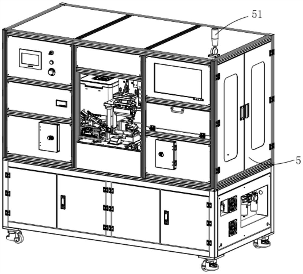
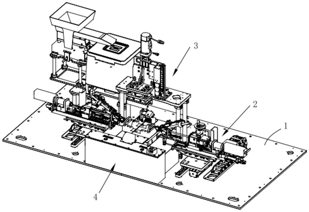
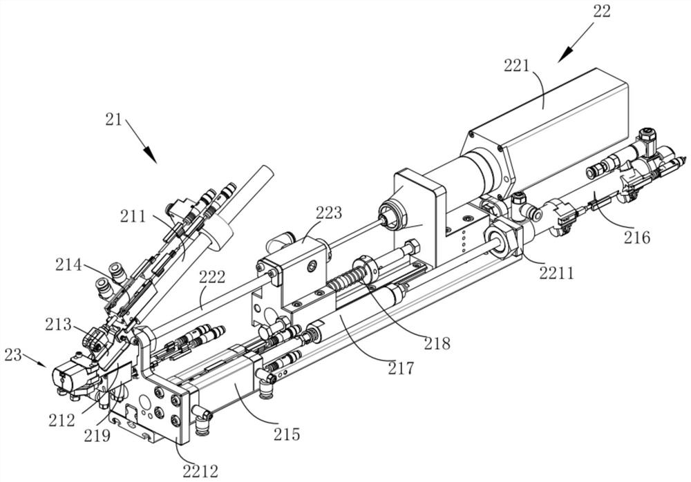
The invention relates to the field of automatic machinery, in particular to a screw locking machine. The screw locking machine mainly comprises a frame body, a carrier module, a press-fit stripping mechanism module and a screw driving module. The carrier module is arranged on the frame body, and the carrier module is used for placing parts; the press-fit stripping mechanism module is movably arranged on the frame body and used for being matched with the carrier module to fix the parts and stripping the parts subjected to screw locking; the press-fit stripping mechanism module is located over the carrier module; and the screw driving module is arranged on the frame body, and the screw driving module can rotate a screw and lock the screw to the part. According to the screw locking machine, manpower is saved, the working efficiency of screw locking is improved, the torsion of each screw can be kept consistent, then it is guaranteed that the screws are evenly stressed in the locking process, the phenomena of screw loosening and inclined screwing are avoided, and therefore the service life of parts is prolonged.

Description

technical field [0001] The invention relates to the field of automatic machinery, in particular to a screw locking machine. Background technique [0002] With the continuous progress of science and technology and the rapid development of economy, micro electrical appliances are more and more popular. In the process of micro electrical appliances production, screws are indispensable parts. In the process of producing micro electrical appliances, in order to facilitate the tight connection of various parts, the process of locking screws is particularly important. The screw locking process in the prior art usually requires manual locking of the screws, which on the one hand reduces the efficiency of screw locking, and on the other hand, in the process of locking the screws, the components will be stressed during the screw locking process. If it is not uniform, it is impossible to ensure that the torque of each screw on the component is consistent, which will lead to screw twis...

Claims


Application Information

Patent Timeline
IPC IPC(8): B23P19/06B25B11/02
CPCB23P19/06B25B11/02
Inventor 郑建生甄华全
Owner 昆山威典电子有限公司
Learn More