Tire

A tire and tire circumferential technology, applied to tire parts, tire tread/tread pattern, transportation and packaging, etc., can solve the problems of affecting the pattern, destroying the rubber, easy to fall out of stones, etc., to maintain uniformity and increase The effect of stone removal ability

Pending Publication Date: 2021-09-21
SHANGHAI TIRE & RUBBER TIRE RES INST +1
View PDF6 Cites 0 Cited by
  • Summary
  • Abstract
  • Description
  • Claims
  • Application Information

AI Technical Summary

Problems solved by technology

[0002] Tire pattern grooves (especially those with large width and depth) are prone to stone inclusion problems. If the stones embedded in the pattern grooves cannot be discharged in time, it will affect the performance of the tread pattern manipulation, wear and drainage, and seriously Destroying the rubber at the bottom of the groove, causing abnormal damage to the tire, and even endangering driving safety
At present, there are many ways to improve the problem of stone inclusion in the pattern groove, such as setting protrusions at the bottom of the pattern groove, and using the elasticity of the protrusions to remove the stones entering the pattern groove; changing the side wall of the pattern groove into two sections, increasing the size of the pattern The inclination angle of the opening part of the side wall of the groove, so that the groove is not easy to trap stones and the stones in the groove are easy to fall out; a stone discharge space with a size slightly larger than the width of the groove is set at the end of the groove or at the turning point of the groove, and the size is larger. The large groove space makes the stone fall off easily
The common disadvantage of the first two is that if the opening width of the groove is not increased, the radius of the chamfering arc at the bottom of the groove is too small, which may easily cause cracks at the bottom of the groove and damage the tire, or the inclination angle of the side wall of the groove is too large. Small, not conducive to stone discharge; if the opening width of the pattern groove is increased, it will affect other performances of the pattern (such as uneven wear, pattern block strength, etc.)
For the first method of setting protrusions at the bottom of the grooves, without increasing the opening width of the grooves, it will also affect the drainage performance of the grooves, and when the grooves are worn to the protrusions, the width of the grooves is obvious Narrowing will affect the performance of the pattern, and it may even be mistaken for the pattern groove has been ground, and it will be discarded in advance
In addition, no matter whether the opening width of the pattern groove is increased or not, the processing difficulty of the vulcanization mold will be increased

Method used


Image

  • Tire
  • Tire
  • Tire

Examples


Embodiment 1

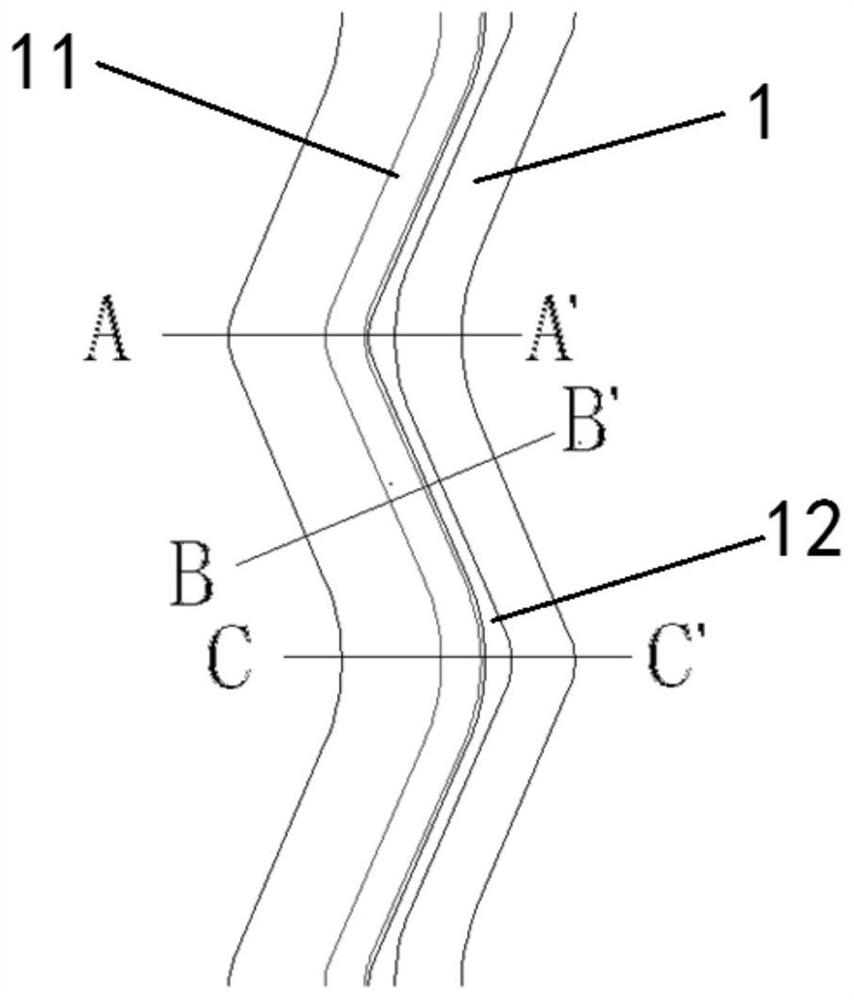
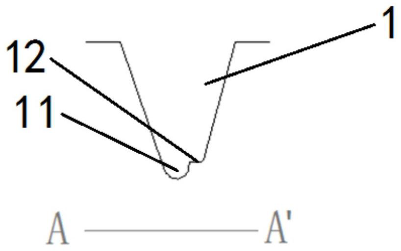
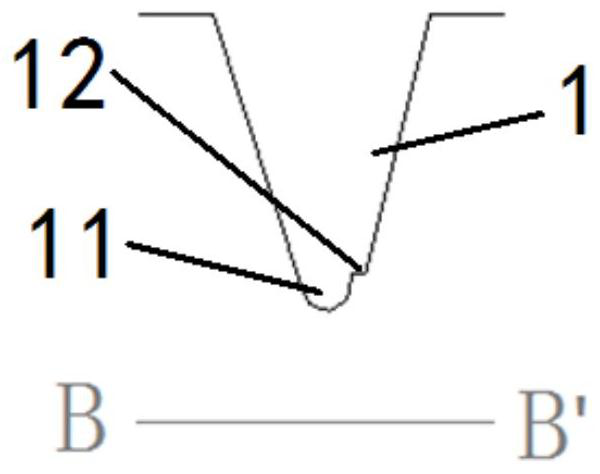
[0023] Such as figure 1 The profile of a zigzag longitudinal groove 1 shown in the figure, the left side of the figure is close to the tire shoulder, and the right side is close to the centerline of the tire circumference. The groove bottom 11 shown in the figure is in a state before rounding, Figure 2~4 for figure 1 A schematic cross-sectional view of a zigzag longitudinal groove shown in FIG.

[0024] Such as Figure 1~4 As shown, the twists and turns of pattern groove 1 are connected by arcs, and the sizes of the arcs on both sides are different, so that the surface width of pattern groove 1 at the turn is greater than the surface width of pattern groove 1 straight line, and the maximum surface width at the turn is the same as the minimum surface of the straight line. The ratio range of the width is 1.1-1.3, and it is 1.15 in this embodiment.

[0025] The inclination angles of the sidewalls on both sides of the groove 1 show a changing trend along the tire circumferenti...

Embodiment 2

[0029] Such as Figure 5 The profile of a zigzag longitudinal groove 1 shown in the figure, the left side of the figure is close to the tire shoulder, and the right side is close to the centerline of the tire circumference. The cross-sectional schematic diagram is similar to embodiment 1.

[0030] Such as Figure 5 As shown, the zigzag part of the groove 1 is connected by a straight line, and the straight lines on both sides are of different lengths, so that the surface width of the zigzag part of the groove is greater than the surface width of the straight line of the groove, and the ratio range of the maximum surface width of the zigzag part to the minimum surface width of the straight line Is 1.1-1.3, the present embodiment is 1.13, other features and dimensions are similar to embodiment 1.

Embodiment 3

[0032] A tire, including a tire running surface and a tire pattern arranged on the tire running surface, the tire pattern includes four zigzag longitudinal grooves 1 arranged along the tire circumference, the maximum surface width of the groove 1 at the zigzag part and the minimum surface of the straight line The width ratio range is 1.1, the sidewall inclination angle at the middle position of the straight line segment is relatively large, the difference range between the maximum inclination angle and the minimum inclination angle of each side wall is 3°, and the average value of the sidewall inclination angle on the side of groove 1 close to the tire shoulder It is greater than the average sidewall inclination angle on the side close to the tire circumferential centerline, and the difference range between the average sidewall inclination angles on both sides is 2°.

[0033] In this embodiment, the height of the groove bottom platform 12 from the groove bottom 11 is 5 mm, the ...


PUM


Abstract

The invention relates to a tire. The tire comprises a tire tread and a tire pattern arranged on the tire tread, wherein the tire pattern comprises a plurality of zigzag longitudinal pattern grooves (1) arranged in the circumferential direction of the tire, and inclination angles of side walls of the two sides of each pattern groove (1) change in the circumferential direction of the tire; the width of a zigzag part of the pattern groove (1) is greater than that of the linear section of the pattern groove (1), and a pattern groove bottom platform (12) is arranged on one side, close to the circumferential center line of the tire, of the groove bottom (11) of the pattern groove (1). Compared with the prior art, by improving and comprehensively applying a traditional stone removing technology, stone embedded in the zigzag longitudinal pattern grooves is reduced, and meanwhile the influence on the pattern drainage performance is extremely small.

Description

technical field [0001] The invention relates to the technical field of vehicle tires, in particular to the tread pattern design technology of pneumatic truck tires, and in particular to the technology of reducing stone embedded in longitudinal zigzag grooves under the premise of minimal impact on tread wear performance and drainage performance. Background technique [0002] Tire pattern grooves (especially those with large width and depth) are prone to stone inclusion problems. If the stones embedded in the pattern grooves cannot be discharged in time, it will affect the performance of the tread pattern manipulation, wear and drainage, and seriously Destroy the rubber at the bottom of the groove, cause abnormal damage to the tire, and even endanger driving safety. At present, there are many ways to improve the problem of stone inclusion in the pattern groove, such as setting protrusions at the bottom of the pattern groove, and using the elasticity of the protrusions to remov...

Claims


Application Information

Patent Timeline
Patent Type & Authority Applications(China)
IPC IPC(8): B60C11/03B60C11/12
CPCB60C11/0302B60C11/1259B60C2011/0337
Inventor 陈振艺
Owner SHANGHAI TIRE & RUBBER TIRE RES INST
Why Eureka
Try Eureka