
A grid-shaped fuel tank

A grid-like and grid-like technology, which is applied in the field of auto parts, can solve problems such as vehicle center of gravity deviation, stress concentration of clapboard and box welds, and influence on driving safety, so as to prevent deformation or cracking and fuel impact. The effect of uniformity and reduction of surge phenomenon

Active Publication Date: 2022-03-29
TONGYA (SHANDONG) AUTOMOBILE TECH GRP CO LTD
View PDF8 Cites 2 Cited by
  • Summary
  • Abstract
  • Description
  • Claims
  • Application Information

AI Technical Summary

Problems solved by technology

[0003] During the driving process of the vehicle, when encountering road bumps, starting and stopping, or turning, the fuel inside the fuel tank will shake and surge forward or backward, which will impact the fuel tank body, causing deformation of the fuel tank or making the fuel tank Cracks in the welded parts lead to oil leakage, which affects driving safety; in addition, the fuel surge will cause the center of gravity of the entire vehicle to shift, directly affecting driving safety, and even fuel spillage occurs; and the fuel surge hits the inner wall of the fuel tank, resulting The noise seriously reduces people's driving experience
[0004] At present, in order to reduce the impact force of the fuel inside the fuel tank, a partition is usually installed inside the fuel tank. In the prior art, the partition is usually welded to the wall of the fuel tank, and the middle part is opened to pass through the oil. However, this welding structure is easy to make the partition and the tank body Stress concentration in the welding seam of the car body, the surge of fuel will cause cracks at the welding position of the partition plate and the box body during the moving process of the car body, and the anti-surge phenomenon is not ideal

Method used


Image

  • A grid-shaped fuel tank
  • A grid-shaped fuel tank
  • A grid-shaped fuel tank

Examples


Embodiment 1

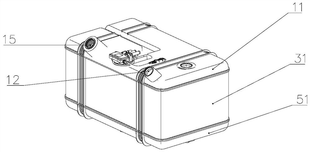
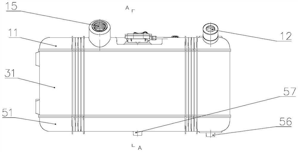
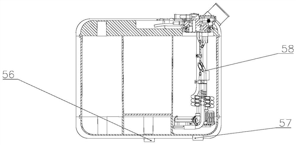
[0056] like Figure 1-10 As shown, Embodiment 1 of the present application discloses a grid-shaped fuel tank, which includes: a fuel tank housing, which surrounds a cavity including a fuel chamber, and the fuel tank housing includes an upper upper housing area, a middle The middle shell area and the lower shell area of ​​the lower part; the middle grid rib 32 structure is set in the cavity corresponding to the height area of ​​the middle shell 31, and the middle grid rib 32 structure divides the middle part of the cavity into several middle grid cavities. The grid cavities are not connected in the radial direction, and the bottom end of the first middle grid cavity group included in the middle grid cavity is provided with an oil opening to communicate with each other to form a fuel cavity. The middle part of the cavity is divided into several middle grid cavities by setting the middle grid rib 32 structure, and the middle grid cavities are not connected in the radial direction...

Embodiment approach

[0075] As an implementation manner, the lower housing area includes side walls and a bottom wall, and the oil flow port 53 extends upward from the connection between the lower grid ribs 52 and the bottom wall. This arrangement can ensure the smooth flow of fuel from the oil flow port 53 .

[0076] Specifically, the structure of the lower grid rib 52 is composed of several lower partitions arranged and connected to form a grid shape. One end of the first lower grid cavity 54 is opened to communicate with the first middle grid cavity 33, and the other end is connected to the lower shell area. connected to the bottom wall.

[0077] Specifically, the lower casing 51 below one of the first middle grid chambers 33 is provided with a boss, and the boss is installed with a fuel drain bolt 56 as a fuel drain port.

[0078] Specifically, the upper casing 11 above one of the first middle grid chambers 33 is provided with a boss, and the boss is used for installing a fuel sensor.

[007...

Embodiment 2

[0092] Such as Figure 1-10 As shown, Embodiment 2 of the present application provides an integrated fuel tank, which includes the grid-shaped fuel tank in Embodiment 1, and the middle grid chamber also includes a second middle grid chamber group, and the first middle grid chamber group The second medium grid cavity group is not connected to each other, and the medium grid cavities in the second medium grid cavity group are connected to each other to form a urea cavity. By setting the second middle mesh chamber group, and the second middle mesh chamber group is not connected with the first middle mesh chamber group, the integrated setting of the fuel chamber and the urea chamber is realized, which reduces the volume of the integrated fuel tank and saves energy. The combined weight of the two makes the vehicle lighter; in addition, by integrating the fuel chamber and the urea chamber, the heat of the fuel chamber can heat the urea chamber, realize the reuse of heat, and avoid t...


PUM


Abstract

The application discloses a grid-shaped fuel tank, which belongs to the field of auto parts. The grid-shaped fuel tank includes: a fuel tank housing that encloses a cavity including a fuel chamber, and the fuel tank housing includes an upper upper housing area, a middle middle housing area, and a lower lower housing area; the middle grid rib structure is set in the cavity corresponding to the middle shell height area, and the middle grid rib structure divides the middle part of the cavity into several middle grid cavities, one of the middle grid cavities There is no communication between them in the radial direction, and the bottom end of the first group of middle mesh chambers included in the middle mesh chambers is provided with oil openings to communicate with each other to form the fuel chamber. The grid-shaped fuel tank does not need to be designed with a separate anti-surge partition, and can significantly reduce the fuel surge; in addition, it can prevent the tank from being deformed or cracked when it is impacted by an external force; in addition, the fuel flows in the lower shell area, Thereby greatly reducing the impact force of fuel flow and weakening the "surge" phenomenon of fuel.

Description

technical field [0001] The application relates to a grid-shaped fuel tank, which belongs to the field of auto parts. Background technique [0002] With the rapid development of the automobile industry and the improvement of automobile environmental protection requirements, the fuel tank is an important safety and regulatory part in automobile parts, and its structure optimization and performance improvement have become a problem that major automobile manufacturers are competing to discuss and solve. [0003] During the driving process of the vehicle, when encountering road bumps, starting and stopping, or turning, the fuel inside the fuel tank will shake and surge forward or backward, which will impact the fuel tank body, causing deformation of the fuel tank or making the fuel tank Cracks in the welded parts lead to oil leakage, which affects driving safety; in addition, the fuel surge will cause the center of gravity of the entire vehicle to shift, directly affecting drivin...

Claims


Application Information

Patent Timeline
Patent Type & Authority Patents(China)
IPC IPC(8): B60K15/03B60K15/077
CPCB60K15/03B60K15/077B60K2015/0775B60K2015/0777B60K2015/0344B60K15/04
Inventor 朱庆凯
Owner TONGYA (SHANDONG) AUTOMOBILE TECH GRP CO LTD
Learn More