Conveying device with self-cleaning function for sludge low-temperature drying
A conveying device and self-cleaning technology, applied in the direction of cleaning devices, conveyors, conveyor objects, etc., can solve the problem of incomplete cleaning of conveyor belts, and achieve the effect of avoiding bumps, enhancing cleaning efficiency and improving cleaning effect.
- Summary
- Abstract
- Description
- Claims
- Application Information
AI Technical Summary
Problems solved by technology
Method used
Image
Examples
Embodiment 1
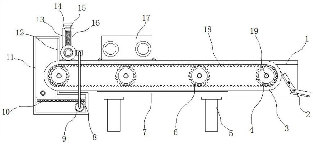
[0026] Example 1: See Figure 1-6 , a transmission device for low-temperature drying of sludge with self-cleaning function, comprising a frame 1 and a connecting bottom plate 7, the bottom between one ends of the frame 1 is fixedly connected with the connecting bottom plate 7, and the four corners of the bottom ends of the connecting bottom plate 7 are respectively fixed Connected with support feet 5, one side between the two ends inside the frame 1 is provided with a material guide structure 2, and the two sides between one end of the frame 1 are respectively movably connected with a guide roller shaft 4, and one end of the guide roller shaft 4 passes through the frame 1 and is fixed A second motor 19 is connected, and a conveyor belt 3 is movably connected between the outer sides of the guide roller shaft 4. The inside of the conveyor belt 3 is fixedly connected with multiple sets of engaging tooth blocks 18, and the middle position between one end of the frame 1 is movably c...
Embodiment 2
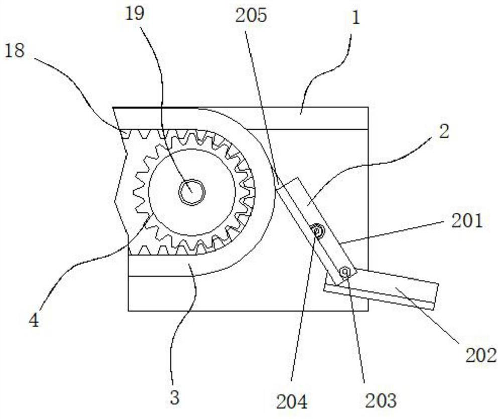
[0029] Embodiment 2: The material guide structure 2 is composed of a main hinge plate 201, a secondary hinge plate 202, a first bolt 203, a second bolt 204 and a rubber sheet 205. The main hinge plate 201 is arranged on one side between one end of the frame 1, and the main hinge plate 201 A second bolt 204 is respectively movably connected between the hinge plate 201 and one end of the frame 1 , a secondary hinge plate 202 is arranged outside the bottom of the main hinge plate 201 , and a first bolt is movably connected between the main hinge plate 201 and the secondary hinge plate 202 203, a rubber sheet 205 is fixedly connected to the top of the main hinge plate 201;
[0030] Specifically, such as figure 1 and figure 2As shown, turn over the main hinge plate 201 and put the top rubber sheet 205 on one side of the conveyor belt 3, and lock the second bolt 204 to fix its angle. The auxiliary hinge plate 202 is also locked by the first bolt 203, and the drop of sludge transm...
Embodiment 3
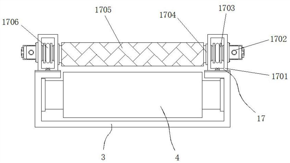
[0031] Embodiment 3: The spreading mechanism 17 is composed of a box body 1701, a first motor 1702, a connecting tooth plate 1703, a through groove 1704, a pressure roller 1705, a chain 1706 and a leading tooth plate 1707, and the box body 1701 is respectively fixedly connected to the top of the frame 1 On one side of the box body 1701, a first motor 1702 is fixedly connected to the middle position of the outer end of the box body 1701. The output end of the first motor 1702 passes through the inner wall of the box body 1701 and is fixedly connected to a main sprocket 1707. The two sides of the box body 1701 One end is respectively movably connected with a connecting toothed disc 1703, and a chain 1706 is movably connected between the connecting toothed disc 1703 and one side of the leading toothed disc 1707. The two sides of one end of the box body 1701 are respectively provided with through grooves 1704, and the connecting toothed disc 1703 A pressure roller 1705 is fixedly c...
PUM
 Abstract
Description
Claims
Application Information
 - R&D
- Intellectual Property
- Life Sciences
- Materials
- Tech Scout
- Unparalleled Data Quality
- Higher Quality Content
- 60% Fewer Hallucinations
Browse by: Latest US Patents, China's latest patents, Technical Efficacy Thesaurus, Application Domain, Technology Topic, Popular Technical Reports.
© 2025 PatSnap. All rights reserved.Legal|Privacy policy|Modern Slavery Act Transparency Statement|Sitemap|About US| Contact US: help@patsnap.com


