Non-contact position detection method
A detection method and non-contact technology, applied in the direction of electric/magnetic position measurement, measuring device, using electric device, etc., can solve the problems of poor electrical contact, wrong position signal, etc., to improve the service life, avoid friction damage, improve The effect of long-term precision
- Summary
- Abstract
- Description
- Claims
- Application Information
AI Technical Summary
Problems solved by technology
Method used
Image
Examples
Embodiment 1
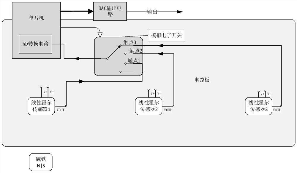
[0038] When the moving device is at position 1, the magnet is closest to the linear Hall sensor 1, the voltage signal output by the linear Hall sensor 1 is greater than the output voltage signals of the linear Hall sensor and the linear Hall sensor 3, and the linear Hall sensor 2 and The linear Hall sensor 3 cannot sense the magnet because it is too far away from the magnet, and the output voltage signal is the same. When the moving device gradually moves to the right to position 2 or position 3, the distance between the linear Hall sensor 1 and the magnet increases. Large, the output voltage signal of the linear Hall sensor 1 gradually decreases; the distance between the linear Hall sensor 2 and the magnet decreases, and the output voltage signal of the linear Hall sensor 2 gradually increases; the linear Hall sensor 3 still cannot sense To the magnet, the output voltage signal of the linear Hall sensor 3 remains unchanged.
Embodiment 2
[0040] When the moving device moves to position 4, the linear Hall sensor 2 is closest to the magnet, and the output voltage signal of the linear Hall sensor 2 is the largest. Since the linear Hall sensor 1 and the linear Hall sensor 3 are far away from the magnet, they cannot sense the magnet. , so the output voltage is the same, when the moving device gradually moves to the right to position 5 or position 6, the distance between the linear Hall sensor 2 and the magnet increases, and the voltage signal output by the linear Hall sensor 2 gradually decreases; linear The distance between the Hall sensor 3 and the magnet decreases, and the voltage signal output by the linear Hall sensor 3 gradually increases; the distance between the linear Hall sensor 1 and the magnet increases further, and the magnet is still not sensed, the linear Hall sensor The output voltage of 1 remains constant.
Embodiment 3
[0042] When the moving device moves to position 7, the linear Hall sensor 3 is closest to the magnet, and the output voltage signal of the linear Hall sensor 3 is the largest. Since the linear Hall sensor 1 and the linear Hall sensor 2 are far away from the magnet, they cannot sense the magnet. , so the output voltage is the same, when the moving device gradually moves to the right to position 8 or position 9, the distance between the linear Hall sensor 3 and the magnet increases, and the voltage signal output by the linear Hall sensor 3 gradually decreases; linear The distance between the Hall sensor 1 and the linear Hall sensor 2 and the magnet further increases, and the voltage signals output by the linear Hall sensor 1 and the linear Hall sensor 2 remain unchanged.
PUM
 Abstract
Description
Claims
Application Information
 - R&D
- Intellectual Property
- Life Sciences
- Materials
- Tech Scout
- Unparalleled Data Quality
- Higher Quality Content
- 60% Fewer Hallucinations
Browse by: Latest US Patents, China's latest patents, Technical Efficacy Thesaurus, Application Domain, Technology Topic, Popular Technical Reports.
© 2025 PatSnap. All rights reserved.Legal|Privacy policy|Modern Slavery Act Transparency Statement|Sitemap|About US| Contact US: help@patsnap.com


