Multi-mode contraceptive ring taking-out device for gynecology department

A technology for taking out a device and a birth control ring, which is applied in the field of medical devices, can solve the problems of not having a radial clamping device and the radial size of the radial clamping device cannot be clamped, and achieves the effect of reducing discomfort

Active Publication Date: 2021-09-24
张晓冬
View PDF12 Cites 0 Cited by
  • Summary
  • Abstract
  • Description
  • Claims
  • Application Information

AI Technical Summary

Problems solved by technology

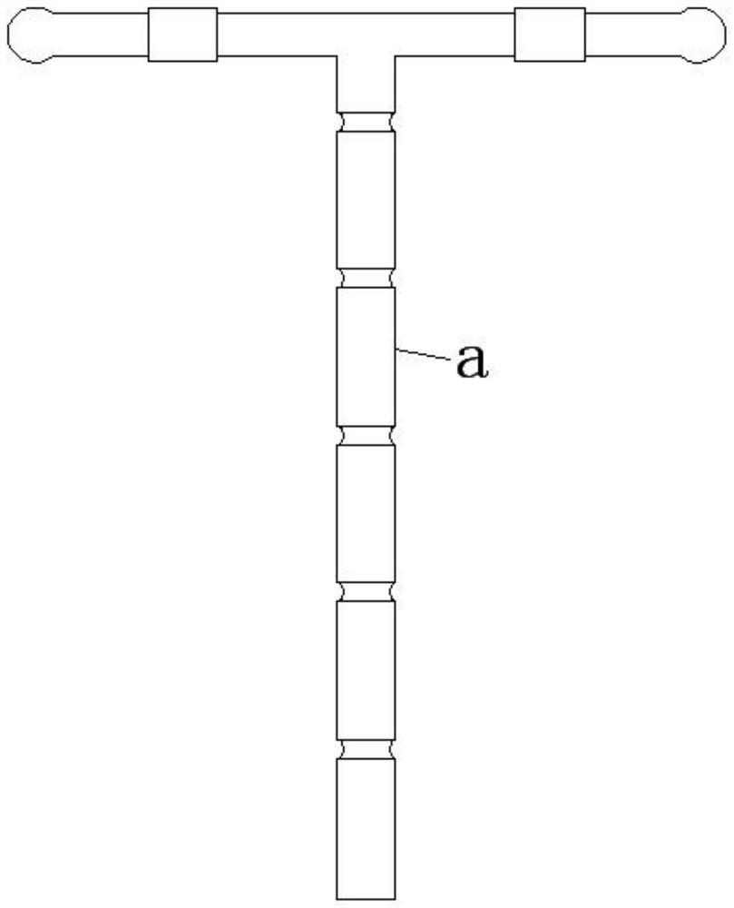
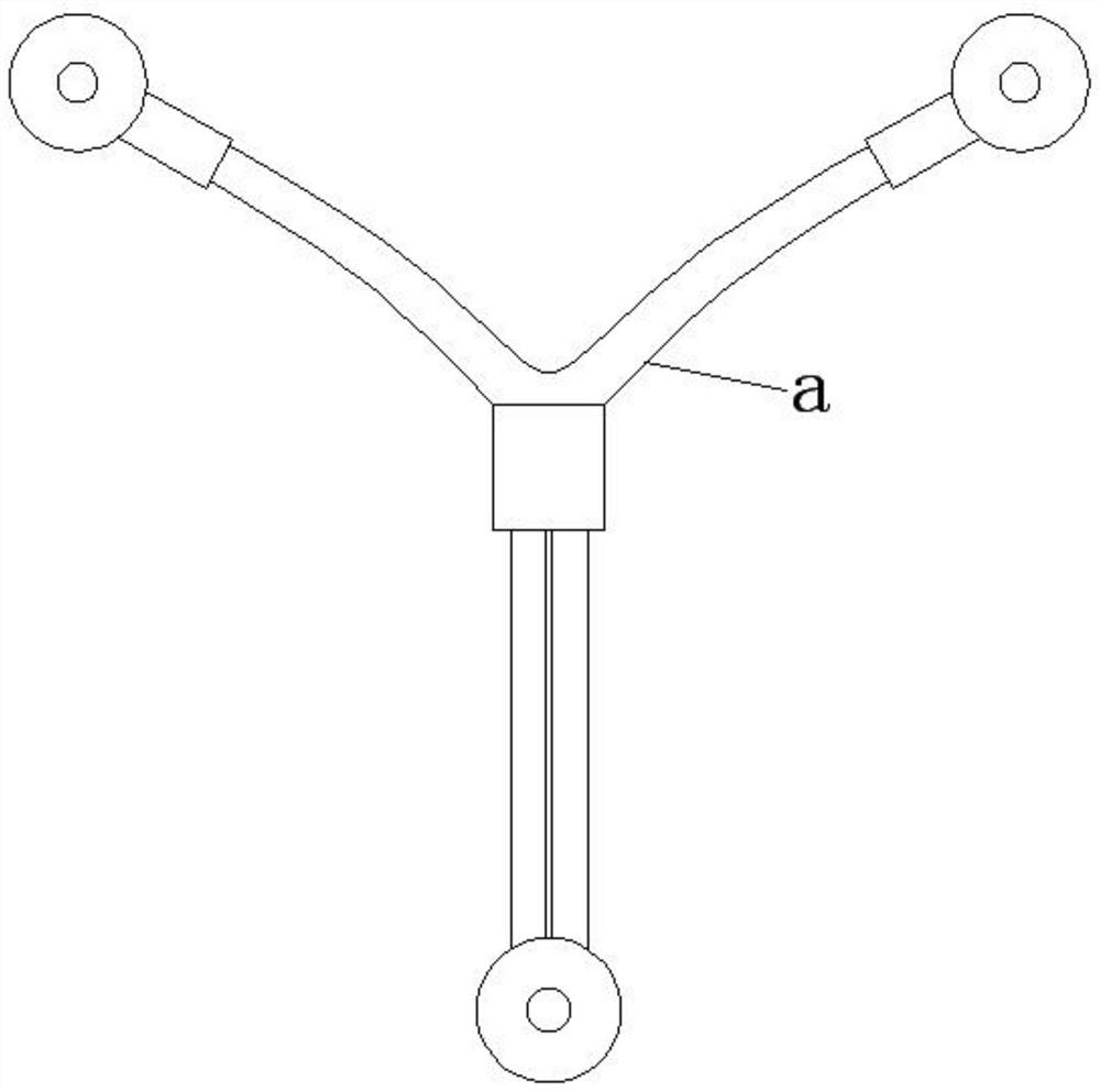
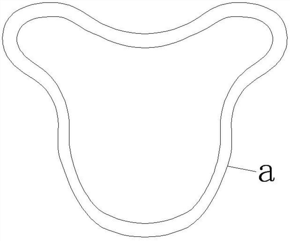
[0003] For birth control rings such as T copper, mother body music, fancy, R-shaped rings, it has at least one rod-shaped end, which makes it easy to be clamped and fixed, while for birth control rings such as Yuangong type, its structure does not have obvious The rod-shaped end presents a round and closed ring shape, and the common radial clamping device is limited in that its radial size is too small to clamp, so it is necessary to design a dual-mode birth control ring removal device that can clamp Holds birth control rings with a rod-shaped end and can hold birth control rings with a rounded and closed structure

Method used


Image

  • Multi-mode contraceptive ring taking-out device for gynecology department
  • Multi-mode contraceptive ring taking-out device for gynecology department
  • Multi-mode contraceptive ring taking-out device for gynecology department

Examples


specific Embodiment

[0069] The dual-mode chuck 2 includes:

[0070] The dual-mode rotor 21 includes a front blind hole 21a formed on the front end of the rod-shaped foundation 1, a limiting convex ring 21b formed on the inner wall of the front blind hole 21a, and a rotatable rotating shaft arranged in the front blind hole 21a. The core barrel 21c, the limit recessed ring 21d formed on the outer wall of the rotating core barrel 21c and matched with the limit convex ring 21b, the front half and the rear half of the inner cavity of the rotating core barrel 21c are provided with a set of adjustable lock cores 21e, The inner wall of the rotating core barrel 21c is also provided with an anti-rotation plug 21f;

[0071] Each group of adjustable lock cores 21e includes at least three adjustable lock cores 21e that are evenly distributed in the inner cavity of the rotating core cylinder 21c in the circumferential direction, and each adjustable lock core 21e includes a radial direction that runs through th...

Embodiment approach

[0098] When the IUD a has a rod-shaped end, step 2 consists of the following steps:

[0099] Step 2.1, the front clamping device 23 starts:

[0100] Under normal conditions, the twisted lever 31b and the enlarged convex ring 31d are at the front end, and the enlarged convex ring 31d triggers a group of adjustable lock cylinders 21e located in the front:

[0101]The enlarged convex ring 31d abuts against the locking insertion rod 21e-3 and the spring retaining ring 21e-4 to make it protrude radially outwards against the damping of the reset compression spring 21e-5, and the locking insertion rod 21e-3 Abut against the inner wall of the front ring 23a to achieve locking fit, and the front clamping device 23 is activated;

[0102] Step 2.2, turning the twist gear lever 31b;

[0103] Step 2.3, front clamping ring a:

[0104] The anti-rotation side hole 31c acts on the anti-rotation plug 21f to drive the rotating core barrel 21c, the limiting concave ring 21d and the front and r...


PUM


Abstract

The invention provides a multi-mode contraceptive ring taking-out device for the gynecology department. The multi-mode contraceptive ring taking-out device comprises a rod-shaped base, a dual-mode chuck, an input device and a switching device, wherein the rod-shaped base is used for stretching into the uterus through the vagina, the dual-mode chuck is arranged at the front end of the rod-shaped base and used for clamping a contraceptive ring, the input device is arranged in the rod-shaped base and used for driving the dual-mode chuck to conduct clamping action, and the switching device is used for adjusting the dual-mode chuck to enable the dual-mode chuck to be switched between two working modes.

Description

technical field [0001] The application relates to the technical field of medical devices, in particular to a device for taking out multi-mode birth control rings for gynecology. Background technique [0002] The birth control ring is a contraceptive device placed in the uterine cavity. Because most of the devices used in the initial stage are ring-shaped, they are usually called birth control rings, also known as intrauterine devices, or IUDs for short. Usually made of stainless steel, plastic, silicone rubber and other materials, the IUD without medicine is called an inert IUD, such as an IUD plus progesterone or copper, which can improve the contraceptive effect, and is called a medicine or active The intrauterine device is one of the types of birth control devices commonly used in my country. There are many types of IUDs. The commonly used ones in China are T-copper, Maternal Music, Fancy, R-ring, Yuangong and so on. [0003] For birth control rings such as T copper, mot...

Claims


Application Information

Patent Timeline
Patent Type & Authority Applications(China)
IPC IPC(8): A61F6/18
CPCA61F6/18
Inventor 韩晓斌
Owner 张晓冬
Why Eureka
Try Eureka