
Automobile sheet metal stamping die and stamping process

A stamping die and sheet metal technology, which is applied in the field of automotive sheet metal stamping dies and stamping technology, can solve the problems of affecting the connection effect of sheet metal parts, easily leaving burrs, and increasing the difficulty of deburring

Pending Publication Date: 2021-09-24
李朝阳
View PDF12 Cites 0 Cited by
  • Summary
  • Abstract
  • Description
  • Claims
  • Application Information

AI Technical Summary

Problems solved by technology

[0003] However, the existing sheet metal needs to cut the edge before stamping, and it is easy to leave burrs. As the stamping process of the sheet metal part is carried out step by step, the edge of the sheet metal will be drawn into the inside by the stamping edge, resulting in The difficulty of subsequent deburring is greatly increased, and without deburring, it will affect the overall appearance of the sheet metal part and the connection effect with subsequent connectors

Method used


Image

  • Automobile sheet metal stamping die and stamping process
  • Automobile sheet metal stamping die and stamping process
  • Automobile sheet metal stamping die and stamping process

Examples


Embodiment Construction

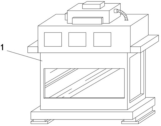
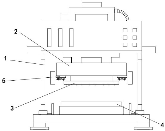
[0033] see Figures 1 to 8 , a schematic diagram of a planar structure and a schematic diagram of a three-dimensional structure of an automobile sheet metal stamping die and a stamping process.

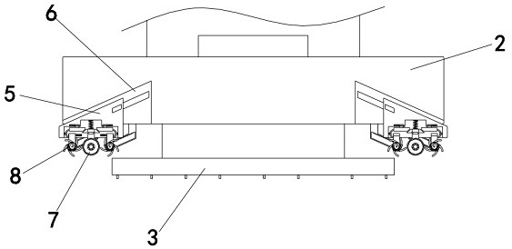
[0034] An automobile sheet metal stamping die and stamping process, comprising a stamping equipment main body 1, an upper mold base 2 is installed on the upper end of the stamping equipment main body 1, a lower mold base 4 is installed on the lower end, a punch 3 is arranged on the lower end of the upper mold base 2, and The lower end of the mold base 4 is equipped with a deburring mechanism 5 corresponding to both sides of the punch 3. The deburring mechanism 5 is equipped with a grinding wheel 7 and a slag collecting device 8. The grinding wheel 7 and the slag collecting device 8 are respectively equipped with a second A limiting frame 9 and a second limiting frame 10, the upper end of the deburring mechanism 5 is equipped with a lateral movement block 11 which is inclined on one si...


PUM


Abstract

The invention relates to the technical field of sheet metal stamping equipment, in particular to an automobile sheet metal stamping die and a stamping process. The automobile sheet metal stamping die comprises a stamping equipment body, an upper die holder is mounted at the upper end inside the stamping equipment body, a lower die holder is mounted at the lower end inside the stamping equipment body, a punch is arranged at the lower end of the upper die holder, and deburring mechanisms are mounted at the two sides, corresponding to the punch, of the lower end of the upper die holder. A polishing rotating wheel and a slag collecting device are arranged in the deburring mechanisms, and the upper end of a first limiting frame is in a trapezoid shape with two inclined sides, so that when the polishing rotating wheel rotates to polish and deburr the edges of sheet metal, acting force can be applied to the polishing rotating wheel along with continuous tilting of the sheet metal, and the polishing rotating wheel and the first limiting frame move upwards, so that an inclined plane drives a transverse moving block to transversely move to apply force to the upper end of a rotating plate, the rotating plate rotates with the middle end as the circle center, the lower end drives a second limiting frame and the slag collecting device to move and be attached to the two sides of the sheet metal, and therefore the situation that chippings fly out to affect the stamping quality of the sheet metal is avoided while deburring is achieved.

Description

technical field [0001] The invention relates to the technical field of sheet metal stamping equipment, in particular to an automobile sheet metal stamping die and a stamping process. Background technique [0002] Cars, with the improvement of people's living standards, have become travel equipment that can be seen everywhere in daily life. When designing and manufacturing cars, a large number of parts such as sheet metal will be used. Sheet metal parts are an important part of auto parts. As large as the car body, as small as the door lock bracket, and many spare parts need to be directly used in one-time forming sheet metal parts. Due to the complex structure and high precision of automobile sheet metal parts, pressure equipment is often used to drive molds for direct stamping. [0003] However, the existing sheet metal needs to cut the edge before stamping, and it is easy to leave burrs. As the stamping process of the sheet metal part is carried out step by step, the edge ...

Claims


Application Information

Patent Timeline
Patent Type & Authority Applications(China)
IPC IPC(8): B21D22/02B21D37/10B21D53/88B24B9/04B24B27/00B24B55/12
CPCB21D53/88B21D37/10B21D22/02B24B9/04B24B27/0076B24B55/12
Inventor 李朝阳
Owner 李朝阳
Learn More