Assembly structure and assembly method for double-power-assisted mechanism of recirculating ball steering gear

An assembly method and steering gear technology, applied to steering mechanisms, electric steering mechanisms, power steering mechanisms, etc., can solve the problems of metal worm gears with large noise, inability to carry large torque, and single structural form, so as to meet the requirements of vehicle assembly and Clearance requirements, reduced motor dimensions, and reduced output torque requirements

Active Publication Date: 2021-09-24
HUBEI HENGLONG AUTOMOTIVE SYST GRP
View PDF10 Cites 4 Cited by
  • Summary
  • Abstract
  • Description
  • Claims
  • Application Information

AI Technical Summary

Problems solved by technology

[0002] At present, the deceleration mechanism used in the electric steering gear commonly used in vehicles is a conventional one-stage worm gear deceleration mechanism. Due to the large noise and low efficiency of the metal worm gear, the worm gear generally uses nylon material with high efficiency and low noise. The worm is made of metal material, but nylon Due to the strength of the material, it cannot carry a large torque. The output torque of this electric steering gear can basically only meet the output torque requirements of light truck commercial vehicles, and cannot meet the torque output requirements of medium and heavy commercial vehicles; on the other hand, due to The structure of the deceleration mechanism used in the existing electric steering gear is single, and often interferes with the outer space of the vehicle, which is difficult to meet the assembly and clearance requirements of different customers. Therefore, it is necessary to improve it

Method used


Image

  • Assembly structure and assembly method for double-power-assisted mechanism of recirculating ball steering gear
  • Assembly structure and assembly method for double-power-assisted mechanism of recirculating ball steering gear
  • Assembly structure and assembly method for double-power-assisted mechanism of recirculating ball steering gear

Examples


Embodiment 1

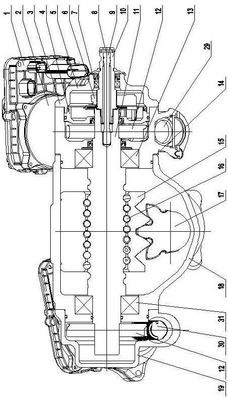
[0037] like figure 1 Shown, the booster A and B are respectively disposed in the booster Global diverter ends;

[0038]First, the input shaft 10 of the dual-boosting mechanism of the circulating ball steering, is fixed to the steering screw assembly. The dual booth of the circulating ball steering is a circulating ball steering body, a booster A and a booster B. The circulating ball switch body includes an input shaft 10, a cylindrical pin 8, a torsion bar 9, a bearing a13, a upper cover 5, an intermediate housing 3, a baffle 4, a shifting spacer 14, a steering screw 11, a mechanical steering body 18, The steering nut 15, the steel ball 16 and the steering arm shaft and the side cover assembly 17. A boreal A29 and a fitting hole B30 are disposed on the steering housing 18 of the circulating ball steering gear body, and the fitting hole A29 is disposed on the steering case 18 on the front end of the circulating ball steering body, and the fitting hole B30 is disposed at the circula...

Embodiment 2

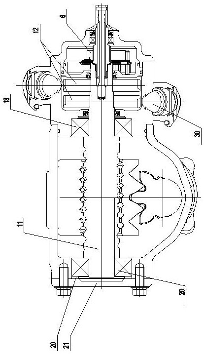
[0044] like figure 2 As shown, the booster A and the booster B are arranged on the end of the end of the global steering end, respectively;

[0045] First, the input shaft 10 of the dual-boosting mechanism of the circulating ball steering, is fixed to the steering screw assembly, and the cylindrical pin 8 is fixed to the steering screw assembly. The dual booth of the circulating ball steering is a circulating ball steering body, a booster A and a booster B. The circulating ball switch body includes an input shaft 10, a cylindrical pin 8, a torsion bar 9, a bearing a13, a upper cover 5, an intermediate housing 3, a baffle 4, a shifting spacer 14, a steering screw 11, a mechanical steering body 18, The steering nut 15, the steel ball 16 and the steering arm shaft and the side cover assembly 17. The bifidoid housing 18 of the circulating ball steering gear body is provided with an assembly hole A29 and a fitting hole B30, and the fitting hole A29 is disposed on the steering housing 1...

Embodiment 3

[0050] like image 3 As shown, the booster A and the booster B are disposed on the upper end of the front end of the global steering.

[0051] First, the input shaft 10 of the dual-boosting mechanism of the circulating ball steering, is fixed to the steering screw assembly, and the cylindrical pin 8 is fixed to the steering screw assembly. The dual booth of the circulating ball steering is a circulating ball steering body, a booster A and a booster B. The circulating ball switch body includes an input shaft 10, a cylindrical pin 8, a torsion bar 9, a bearing a13, a upper cover 5, an intermediate housing 3, a baffle 4, a shifting spacer 14, a steering screw 11, a mechanical steering body 18, The steering nut 15, the steel ball 16 and the steering arm shaft and the side cover assembly 17. A boreal A29 and a fitting hole B30 are provided on the steering housing 18 of the circulating ball steering gear body, and the fitting hole A29 is disposed on the front end of the circulating ball ...


PUM


Abstract

The invention relates to an assembly structure and an assembly method of a double-power-assisted mechanism of a recirculating ball steering gear. The invention belongs to the field of commercial vehicle electric power steering gears. The double-power-assisted mechanism is adopted on the recirculating ball type mechanical steering gear, and due to the fact that the double-power-assisted mechanism is adopted, when the output torque is low, the transmission ratio of the speed reducing mechanism can be reduced, and therefore the boundary dimension of the speed reducing mechanism is reduced; or the transmission ratio of the reducing mechanism is kept unchanged, the motor output torque requirement is reduced, and the motor cost and the motor appearance size can be greatly reduced. When the output torque is high, the requirement for the transmission ratio of a single speed reducing mechanism can be lowered, and the problems that the transmission ratio of a super-large speed reducing mechanism is caused by the requirement for the output torque, the appearance size is large due to the super-large transmission ratio of the speed reducing mechanism, and the strength of the speed reducing mechanism is sacrificed for reducing the appearance are solved.

Description

Technical field [0001] The present invention relates to a method of assembly structure and assembly bis recirculating ball steering assist mechanism; genus commercial EPAS art. Background technique [0002] At present, the speed reduction mechanism of the electric steering vehicle commonly used as used for the deceleration in the form of a conventional a worm mechanism, since the large metal worm gear noise and low efficiency, high worm general efficiency, low noise nylon material, the worm using a metal material, but nylon problems due to material strength, can not carry a large torque, the output torque of this electric steering system can substantially meet the requirements of commercial light truck output torque may not be satisfied, the torque output of heavy-duty commercial vehicles required; while on the other hand, since the conventional electric steering speed reduction mechanism used in the form of a single structure, and tend to interfere with each space vehicle shape,...

Claims


Application Information

Patent Timeline
Patent Type & Authority Applications(China)
IPC IPC(8): B62D5/04
CPCB62D5/04B62D5/046B62D5/0454
Inventor 聂敏傅早清赵波任树王庆军孔真斌侯学为
Owner HUBEI HENGLONG AUTOMOTIVE SYST GRP
Why Eureka
Try Eureka