
Multifunctional optical cable tensile testing machine

A tensile testing machine and multi-functional technology, which is applied in the direction of applying stable tension/pressure to test the strength of materials, measuring devices, instruments, etc. Strength and other issues, to achieve the effect of increasing fixation, increasing stability, and reducing the process of manual operation

Active Publication Date: 2021-09-24
镇江市玖润光通信技术有限公司
View PDF9 Cites 1 Cited by
  • Summary
  • Abstract
  • Description
  • Claims
  • Application Information

AI Technical Summary

Problems solved by technology

[0003] In the prior art, the two ends of the general optical cable need to be fixed during the tensile test. However, the general fixing method is carried out by manually rotating the positioning structure, but this positioning method not only easily leads to low fixability, but also increases The working intensity of the staff, in addition, the optical cable is directly exposed to the outside world during the tensile test, so it is easy to cause the optical cable to fly out and draw the staff when it is accidentally broken. In order to solve the above problems, the present invention provides a multifunctional Optical cable tensile testing machine

Method used


Image

  • Multifunctional optical cable tensile testing machine
  • Multifunctional optical cable tensile testing machine
  • Multifunctional optical cable tensile testing machine

Examples


Embodiment Construction

[0030] The following will clearly and completely describe the technical solutions in the embodiments of the present invention with reference to the accompanying drawings in the embodiments of the present invention. Obviously, the described embodiments are only some, not all, embodiments of the present invention. Based on the embodiments of the present invention, all other embodiments obtained by persons of ordinary skill in the art without making creative efforts belong to the protection scope of the present invention.

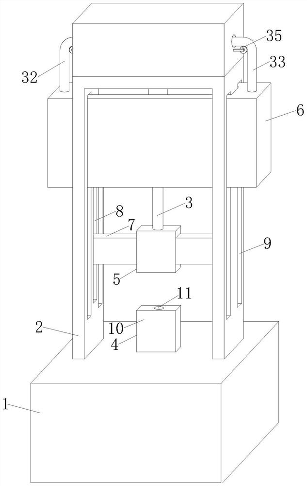
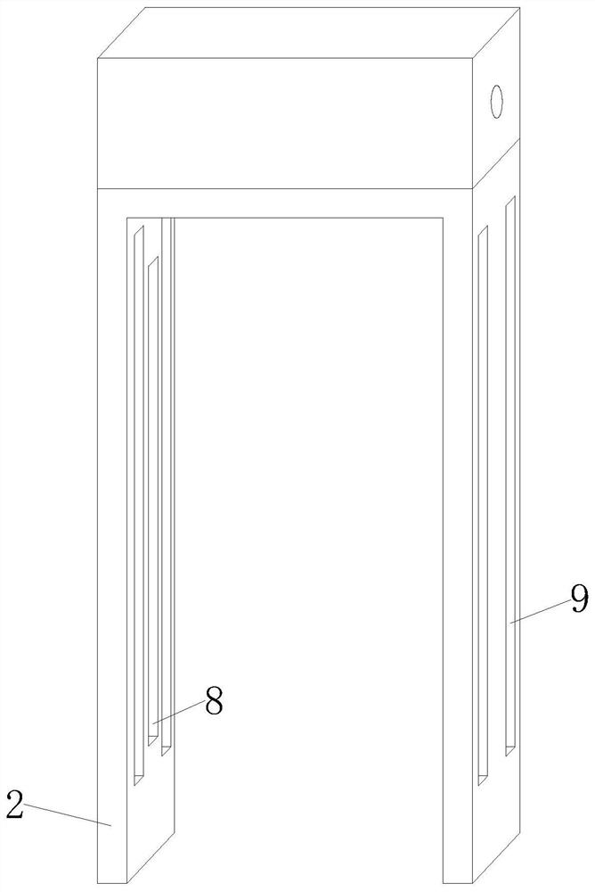
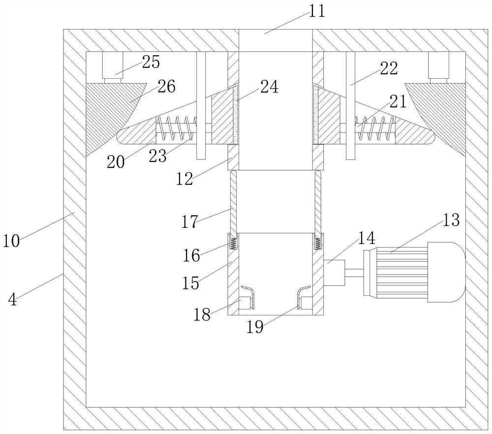
[0031] see Figure 1-5 , a multifunctional optical cable tensile testing machine, including a base 1, the surface of the base 1 is provided with a fixed frame 2, and the inner top of the fixed frame 2 is fixedly provided with a cylinder 3, and the model of the cylinder 3 can be DSNU-16-25 , the surface of the base 1 and the bottom of the cylinder 3 are respectively fixed with a first positioning structure 4 and a second positioning structure 5, the internal st...


PUM


Abstract

The invention discloses a multifunctional optical cable tensile testing machine, and relates to the technical field of optical cable testing. The machine comprises a base, a fixing frame is arranged on the surface of the base, an air cylinder is fixedly arranged on the top of the inner side of the fixing frame, a first positioning structure and a second positioning structure are fixedly arranged on the surface of the base and the bottom of the air cylinder respectively, a protective cover is movably arranged on the surface of the fixing frame, and the first positioning structure comprises a positioning box; and a first motor is fixedly mounted in the positioning box, and an output shaft of the first motor is fixedly connected with a connecting block. Two fixing plates are arranged to perform relative movement, so that one end of an optical cable can be preliminarily clamped by the two fixing plates, then a connecting block rotates, so that the connecting block drives a rotating cylinder to rotate, and the rotating cylinder can rotate and wind one end of the optical cable, so that the fixing effect is achieved; and one end of the optical cable is fixedly arranged in the positioning structure, so that the manual operation process is reduced.

Description

technical field [0001] The invention relates to the technical field of optical cable testing, in particular to a multifunctional optical cable tensile testing machine. Background technique [0002] The communication optical cable is composed of a cable core and an outer sheath composed of several optical fibers. It is widely used in signal transmission in various departments such as telecommunications, electric power, and broadcasting. It is currently the most promising communication transmission medium. The stretching device detects the tensile data of the optical cable and the separate pressure device detects the pressure data of the optical cable. [0003] In the prior art, the two ends of the general optical cable need to be fixed during the tensile test. However, the general fixing method is carried out by manually rotating the positioning structure, but this positioning method not only easily leads to low fixability, but also increases The working intensity of the sta...

Claims


Application Information

Patent Timeline
Patent Type & Authority Applications(China)
IPC IPC(8): G01N3/02G01N3/04G01N3/10
CPCG01N3/02G01N3/04G01N3/10
Inventor 谭伟
Owner 镇江市玖润光通信技术有限公司
Learn More