Thrust cylindrical roller bearing outer ring inner raceway machining device and using method thereof

A cylindrical roller bearing and processing device technology, applied in positioning devices, metal processing equipment, metal processing machinery parts, etc., can solve problems such as hidden safety hazards, difficulty in processing debris in the storage groove, and accidental shaking of the outer ring of the bearing. The effect of improving usability

Pending Publication Date: 2021-09-28
JIANGSU QIANCHAO BEARING
View PDF6 Cites 2 Cited by
  • Summary
  • Abstract
  • Description
  • Claims
  • Application Information

AI Technical Summary

Problems solved by technology

[0003] 1. The processing equipment for the inner raceway of the outer ring of thrust cylindrical roller bearings currently on the market generally has the situation that the outer ring of the bearing is difficult to fix, resulting in the outer ring of the bearing being easily shaken accidentally during the processing process, and the accuracy of fixing the outer ring of the bearing is not good. High, which seriously affects the processing accuracy of the outer ring of the finished thrust cylindrical roller bearing; The outer ring of the bearing is easily damaged during the process of putting in and taking it out. At the same time, the staff often need to go deep into the processing equipment to take it out or put it in, so there are serious safety hazards, and the processing debris inside the storage tank is also difficult to clean up in time; therefore, it is necessary to Design of a thrust cylindrical roller bearing outer ring inner raceway processing device and its application method

Method used


Image

  • Thrust cylindrical roller bearing outer ring inner raceway machining device and using method thereof
  • Thrust cylindrical roller bearing outer ring inner raceway machining device and using method thereof
  • Thrust cylindrical roller bearing outer ring inner raceway machining device and using method thereof

Examples


Embodiment Construction

[0032] In order to make the technical means, creative features, goals and effects achieved by the present invention easy to understand, the present invention will be further described below in conjunction with specific embodiments.

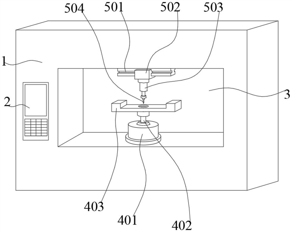
[0033] Such as Figure 1-5 As shown, a thrust cylindrical roller bearing outer ring inner raceway processing device and its use method include a base 1, a supporting mechanism, a processing mechanism and an engaging mechanism, and the outer surface of the base 1 is provided with an open end forward processing groove 3, and the outer wall of the opening end of the processing groove 3 is provided with a controller 2, the inner wall of the bottom surface of the processing groove 3 is provided with a support mechanism, and the upper surface of the support mechanism is provided with a snap-fit ​​mechanism, and the top surface of the processing groove 3 The inner wall of the surface is equipped with a processing mechanism;

[0034] The supporting mechani...


PUM


Abstract

The invention discloses a thrust cylindrical roller bearing outer ring inner raceway machining device and a using method thereof. The thrust cylindrical roller bearing outer ring inner raceway machining device comprises a base, a supporting mechanism, a machining mechanism and a clamping mechanism, wherein a machining groove with a forward opening end is formed in the outer surface of the base, a controller is arranged on the outer wall of the opening end of the machining groove, the supporting mechanism is installed on the inner wall of the bottom face of the machining groove, the clamping mechanism is arranged on the upper surface of the supporting mechanism, and the machining mechanism is installed on the inner wall of the top face of the machining groove. Through the clamping mechanism, a thrust cylindrical roller bearing outer ring is clamped and fixed in the mode that limiting is conducted firstly and then magnetic attraction fixing is conducted, and the device is suitable for stably and reliably clamping and fixing bearing outer rings of various different sizes; and through the supporting mechanism, the thrust cylindrical roller bearing outer ring can be conveniently put in and taken out before and after machining operation of the device, potential safety hazards are eliminated, machining chippings in a storage groove can be timely cleaned, and thus the device is suitable for being widely used and popularized.

Description

technical field [0001] The invention relates to the technical field of thrust cylindrical roller bearing processing equipment, in particular to a thrust cylindrical roller bearing outer ring inner raceway processing device and a use method thereof. Background technique [0002] Thrust cylindrical roller bearings are often combined into a high rigidity bearing arrangement, which can withstand heavy loads and vibration loads without difficulty; such bearings can withstand large axial loads in one direction, but cannot withstand radial loads, they do not have self-adjusting The thrust cylindrical roller bearing with central capacity can be divided into thrust cylindrical roller and cage assembly, shaft ring and seat ring; 811 series and 812 series thrust cylindrical roller bearings are composed of thrust cylindrical roller and cage assembly, shaft ring and seat The most important parts are thrust cylindrical roller and cage assembly. [0003] 1. The processing equipment for th...

Claims


Application Information

Patent Timeline
Patent Type & Authority Applications(China)
IPC IPC(8): B23C3/34B23C9/00B23Q3/154
CPCB23C3/34B23C9/00B23Q3/1543
Inventor 江钰殷秋香程义清
Owner JIANGSU QIANCHAO BEARING
Why Eureka
Try Eureka