
Combined oil cylinder of tire hydraulic vulcanizing machine and working method of combined oil cylinder

A combination of oil cylinder and vulcanizing machine technology, which is applied to tires, other household appliances, household appliances, etc., can solve the problems of mold opening and closing and clamping cylinders, such as crowded, large space occupation, and slow mold closing speed, so as to save equipment costs, Small footprint and compact structure

Pending Publication Date: 2021-09-28
福建省益震科技有限公司
View PDF3 Cites 0 Cited by
  • Summary
  • Abstract
  • Description
  • Claims
  • Application Information

AI Technical Summary

Problems solved by technology

[0002] The mold opening and closing and locking of the tire hydraulic vulcanizer are controlled by oil cylinders. Most of them divide the mold opening and closing cylinders and the mold locking cylinders into two sets of cylinder structures. There are the following problems: 1. Due to the relatively large bore of the mold opening and closing cylinders, and The structure is similar to that of ordinary thrust cylinders, so the mold closing speed is relatively slow; 2. The mold opening and closing and clamping cylinders are crowded, occupying a large space, poor correlation, incoherent actions and poor coordination

Method used


Image

  • Combined oil cylinder of tire hydraulic vulcanizing machine and working method of combined oil cylinder
  • Combined oil cylinder of tire hydraulic vulcanizing machine and working method of combined oil cylinder
  • Combined oil cylinder of tire hydraulic vulcanizing machine and working method of combined oil cylinder

Examples


Embodiment Construction

[0017] It should be noted that the following detailed description is exemplary and is intended to provide a further description of the present application. Unless otherwise indicated, all technical and scientific terms used herein have the same meaning as commonly understood by those skilled in the art of this application.

[0018] It should be noted that the terms used herein are intended to describe specific embodiments, and not intended to limit the exemplary embodiments of the present application. As used herein, unless the context further clearly indicates that the singular form is intended to include a plural form, but it should be understood that when the term "including" and / or "including" is used in this specification, it indicates There is a combination of features, steps, operations, devices, components, and / or their combinations.

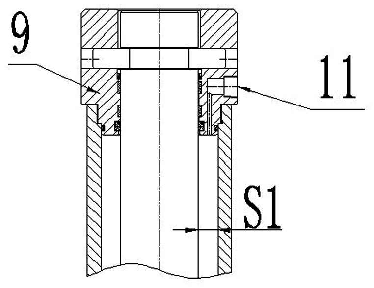
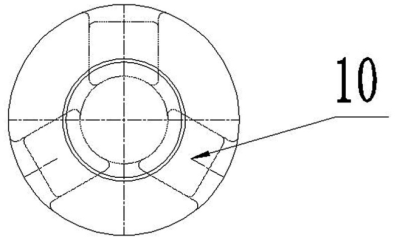
[0019] like Figure 1 ~ 4 As shown, a tire hydraulic vulcanizing machine combined cylinder comprises opening a co-cylinder cylinder 1, t...


PUM


Abstract

The invention relates to a combined oil cylinder of a tire hydraulic vulcanizing machine and a working method of the combined oil cylinder. The combined oil cylinder comprises a mold opening and closing oil cylinder body, and the lower end of the mold opening and closing oil cylinder body is sleeved with a mold locking oil cylinder body and can slide up and down relative to the mold opening and closing oil cylinder body; a mold locking oil cylinder piston which is connected to the mold opening and closing oil cylinder body and divides an inner cavity of the mold locking oil cylinder body into an upper oil cavity and a lower oil cavity is arranged in the mold locking oil cylinder body; a mold opening and closing oil cylinder piston which divides the inner cavity of the mold opening and closing oil cylinder body into the upper oil cavity and the lower oil cavity is arranged in the mold opening and closing oil cylinder body; and the lower end of the mold opening and closing oil cylinder piston is connected to a push-pull rod penetrating out of the lower end of the mold opening and closing oil cylinder body. The combined oil cylinder of the tire hydraulic vulcanizing machine is compact in structure, small in occupied space, easy to install, capable of saving equipment cost, good in mold closing and mold locking action continuity, capable of saving action time and capable of improving equipment efficiency.

Description

Technical field [0001] The present invention relates to the field of tire vulcanization machines, particularly a tire hydraulic vulcanizing machine combined cylinder and its working method thereof. Background technique [0002] The tire hydraulic vulcanizer is opened and the mode, which is controlled by the cylinder control. It is to divide the opening and co-mold cylinder and the latch cylinder into two sets of cylinder structure, and there is a problem: 1. Since the opening and co-cylinder block is relatively large, and The structure is similar to the conventional thrust cylinder structure, and the stiff coil is slow; 2, the opening and closing die and the latch cylinder are crowded, the occupancy is large, the correlation is poor, the action is not coherent and coordinated. Inventive content [0003] In view of this, it is an object of the present invention to provide a compact tire hydraulic vulcanizing machine combined cylinder and its working method, which can save equipme...

Claims


Application Information

Patent Timeline
Patent Type & Authority Applications(China)
IPC IPC(8): B29D30/06B29C33/20
CPCB29D30/0601B29C33/20
Inventor 谢义忠汪鹏
Owner 福建省益震科技有限公司
Learn More