
Vehicle redundant braking system

A brake system and wheel brake technology, which is applied to brake control systems, brakes, brake components, etc., can solve the problems of complex oil circuit structure of the brake system, difficulties in manufacturing, inspection and maintenance, and high cost of the brake system. Achieve the effects of reducing the setting of control valves, saving costs, and simplifying the connection of oil circuits

Inactive Publication Date: 2021-09-28
CHINA AUTOMOTIVE INNOVATION CORP
View PDF6 Cites 3 Cited by
  • Summary
  • Abstract
  • Description
  • Claims
  • Application Information

AI Technical Summary

Problems solved by technology

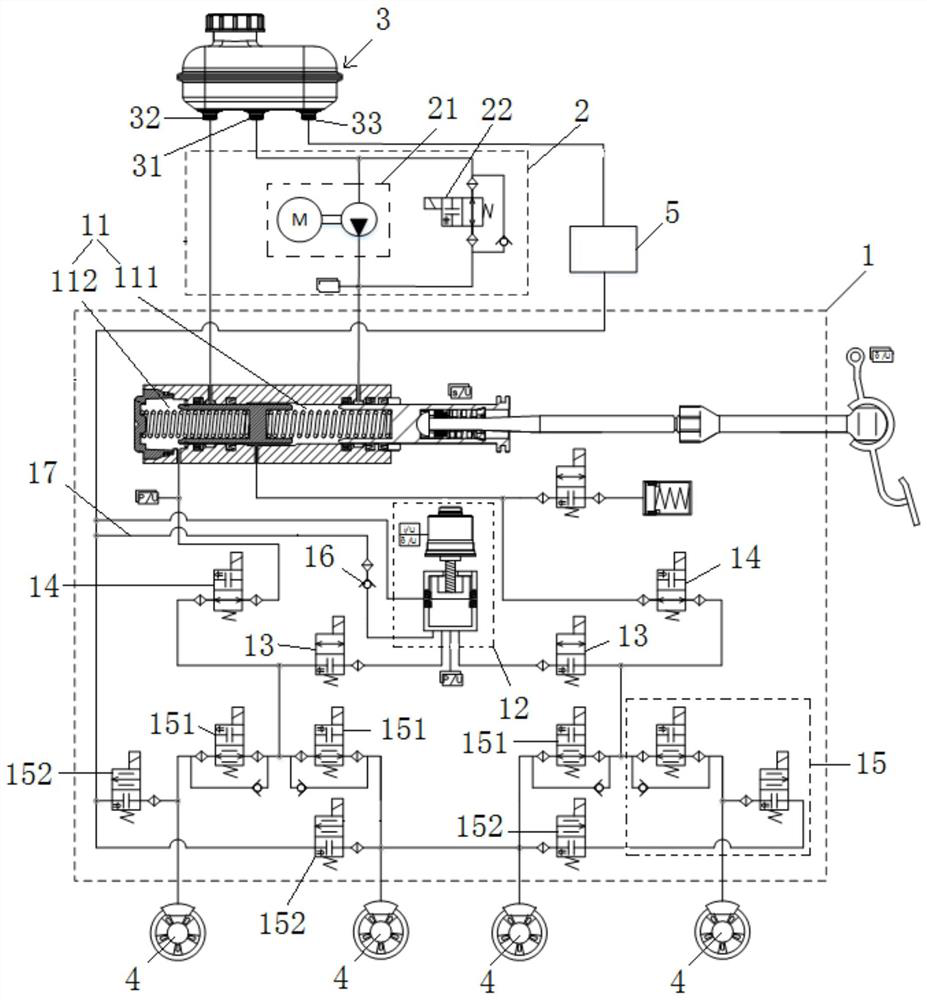
[0004] It can be seen that the existing redundant brake unit is cross-connected or shares part of the oil circuit with the internal oil circuit of the main brake unit. Therefore, it is usually necessary to set up a complicated connection oil circuit between the redundant pressure building module and the booster valve. Correspondingly, multiple control valves need to be set up on the oil circuit, which leads to a more complicated oil circuit structure of the entire braking system, making it difficult to manufacture, inspect and maintain. In addition, the high price of the control valve also leads to the failure of the entire braking system. higher cost

Method used


Image

  • Vehicle redundant braking system

Examples


Embodiment Construction

[0040] All features disclosed in this specification, or steps in all methods or processes disclosed, may be combined in any manner, except for mutually exclusive features and / or steps.

[0041] Any feature disclosed in this specification, unless specifically stated, can be replaced by other alternative features that are equivalent or have similar purposes. That is, unless expressly stated otherwise, each feature is one example only of a series of equivalent or similar features. Throughout the specification, like reference numerals refer to like elements.

[0042] In order to make the technical problems solved by the present invention, the technical solutions adopted and the technical effects achieved clearer, the technical solutions of the present invention will be further described below in conjunction with the accompanying drawings and through specific implementation methods.

[0043] The braking system includes main braking unit, redundant braking unit and wheel cylinder. ...


PUM


Abstract

The invention discloses a vehicle redundant braking system, and belongs to the technical field of vehicle braking. The vehicle redundant braking system comprises a liquid storage tank. a wheel brake; a main brake unit, which comprises a main cylinder, wherein the main cylinder comprises a hydraulic cavity, the liquid storage tank is used for supplying oil to the hydraulic cavity, and the hydraulic cavity is driven by a brake pedal to convey the oil to the wheel brake; a redundant braking unit which comprises a redundant pressure buildup module, and the liquid storage tank is used for supplying oil to the redundant pressure buildup module, wherein the output end of the redundant pressure buildup module is connected with the hydraulic cavity so that oil can be conveyed to the wheel brake. The system has the advantages of being simple in oil way structure and low in brake cost.

Description

technical field [0001] The invention relates to the technical field of vehicle braking, in particular to a vehicle redundant braking system. Background technique [0002] With the promulgation of the autonomous driving regulation SAE J3016_201806, new requirements are put forward for the braking system of L3 and above, that is, the braking system of L3 and above is required to be equipped with the main braking unit for auxiliary braking. The redundant braking unit used for backup, in the case of failure of the main pressure building function of the main braking unit, the redundant braking unit is required to replace the main braking unit to perform the redundant pressure building function, so as to perform normal braking, so as to Execute the instructions of the automatic driving system. [0003] At present, the main braking unit of the braking system includes a booster valve connected to the wheel cylinder, and the redundant braking unit includes a redundant pressure build...

Claims


Application Information

Patent Timeline
Patent Type & Authority Applications(China)
IPC IPC(8): B60T13/14
CPCB60T13/148B60T13/147B60T2270/413
Inventor 张杰王权肖道清李虎本赵佳婧
Owner CHINA AUTOMOTIVE INNOVATION CORP
Learn More