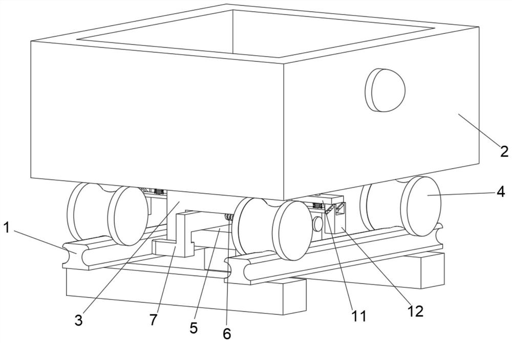
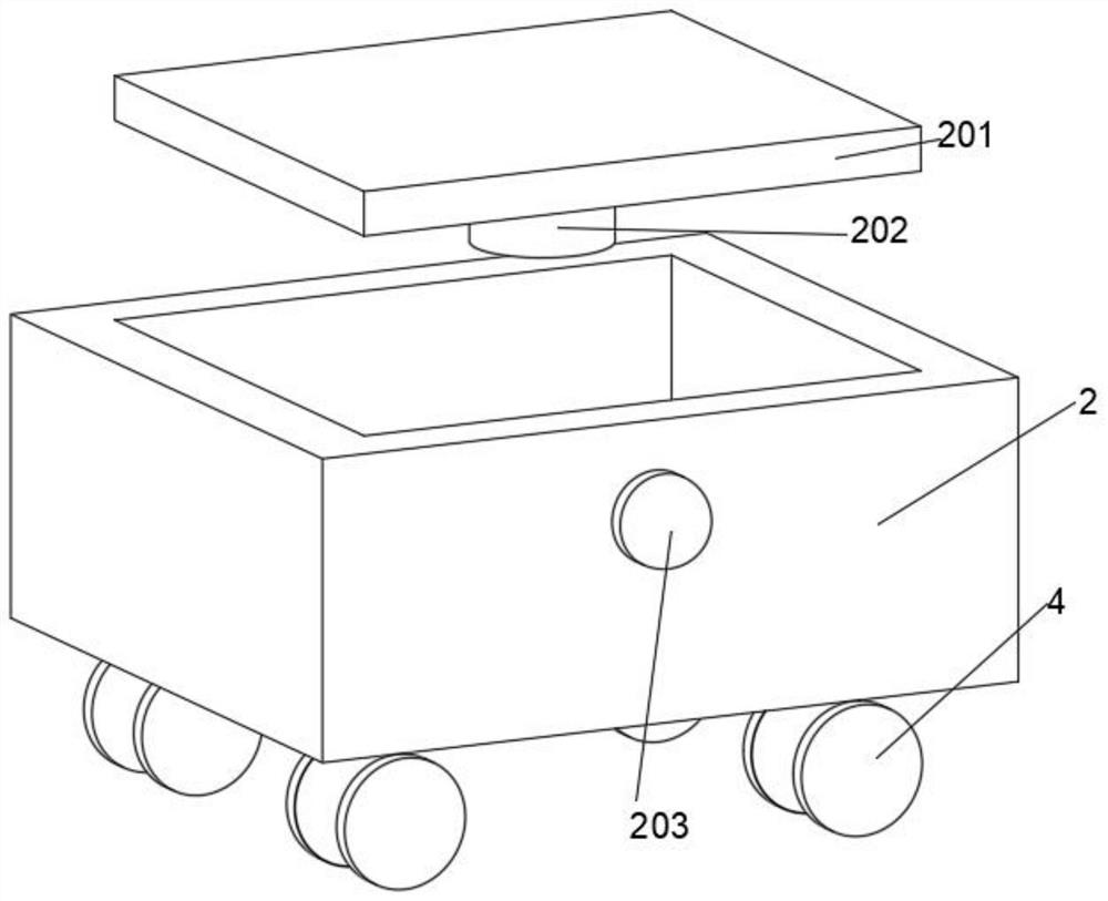
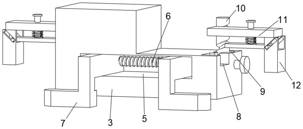
Battery car anti-slip device for shield construction

A battery car and anti-slip technology, which is applied to the braking, transportation and packaging, railway car body parts, etc., where the braking element interacts with the track, can solve the problems of limited locking capacity, slipping cars, and overloaded transportation of feeding cars. , to achieve the effect of improving friction and preventing slipping

Active Publication Date: 2021-09-28
CHINA CONSTR FOURTH ENG DIV
View PDF9 Cites 3 Cited by
  • Summary
  • Abstract
  • Description
  • Claims
  • Application Information

AI Technical Summary

Problems solved by technology

In subway shield construction, transportation in the tunnel is a very important link in the overall construction. During shield construction, the transportation in the tunnel mainly relies on battery locomotives as power to carry muck trucks, slurry cars, segment cars, etc. in the tunnel. In the process of shield excavation, when it is necessary to load the feed truck with soil and other materials, when the feed truck is located on the slope, due to the relatively simple structure of the existing feed truck, when the feed truck is on the slope, there will be In the case of a slipping car, the slipping car will cause harm to the equipment and personnel in the construction below. At the same time, because the existing feeding car is not convenient to control the weight of the material, the problem of overloading the feeding car will occur, which further increases the possibility of rolling away;
[0003] In the track anti-rolling car device in the existing patent technology, for example CN211281027U, the left and right double clamp arms are used to lock the vehicle under braking. The vehicle under braking is locked on the track, but the above-mentioned device can only perform single friction braking on the track, and its locking ability is limited. Immediately canceled, so that when the power of the transport vehicle is not fully utilized, it is still prone to a short-term car slipping phenomenon in the initial stage

Method used


Image

  • Battery car anti-slip device for shield construction
  • Battery car anti-slip device for shield construction
  • Battery car anti-slip device for shield construction

Examples


Embodiment Construction

[0027] In describing the present invention, it should be understood that the terms "center", "longitudinal", "transverse", "length", "width", "thickness", "upper", "lower", "front", " Orientation indicated by rear, left, right, vertical, horizontal, top, bottom, inside, outside, clockwise, counterclockwise, etc. The positional relationship is based on the orientation or positional relationship shown in the drawings, and is only for the convenience of describing the present invention and simplifying the description, rather than indicating or implying that the referred device or element must have a specific orientation, be constructed and operated in a specific orientation, Therefore, it should not be construed as limiting the invention.

[0028] In the description of the present invention, "plurality" means two or more, unless otherwise specifically defined.

[0029] In the description of the present invention, it should be noted that, unless otherwise specified and limited, t...


PUM


Abstract

The invention discloses a storage battery car anti-slip device for shield construction, and belongs to the field of subway shield construction. The storage battery car anti-slip device for shield construction comprises a track. A feeding trolley is arranged above the track; a screw rod groove is formed in the left outer wall of the fixing plate; a screw rod is arranged in the screw rod groove, and two supporting legs are symmetrically arranged on the outer wall of the screw rod front and back; a placement groove is formed in the inner wall of the right side of each limiting groove; An adjusting assembly is arranged in the placing groove; a moving plate is arranged in the limiting groove; an auxiliary clamping assembly is arranged on the bottom face of the outer end of the movable plate. And by arranging the supporting legs, when the feeding trolley stops, the rotating handle drives the lead screw to rotate, so that the lead screw drives the supporting legs in threaded connection to move. Due to the fact that the outer wall of the lead screw is provided with the external threads opposite in screwing direction, the two supporting legs move towards the two sides, the ends of the supporting legs abut against the inner wall of the track, and friction force is generated. Therefore, the stopped feeding trolley can be kept stable, and slippery is avoided.

Description

technical field [0001] The invention relates to the field of subway shield construction, and more specifically relates to an anti-rolling device for battery cars used in shield construction. Background technique [0002] Subway shield tunneling is an important construction technology in urban subway construction, and it is a construction method for digging tunnels underground. It uses the subway shield machine to excavate underground, while preventing the soft ground excavation surface from collapsing or maintaining the stability of the excavation surface, while safely performing tunnel excavation and lining operations inside the machine. The construction process needs to excavate a shaft or a foundation pit at one end of a certain section of the tunnel, hoist the subway shield machine into the installation, and the subway shield machine starts to excavate from the wall opening of the shaft or foundation pit and advances along the designed hole line until To reach the end o...

Claims


Application Information

Patent Timeline
Patent Type & Authority Applications(China)
IPC IPC(8): B61H7/06B61H7/12B61K13/00
CPCB61H7/06B61H7/12B61K13/00
Inventor 麻歆王军华张宝刚陈晓军王立家
Owner CHINA CONSTR FOURTH ENG DIV
Why Eureka
Try Eureka