Engine compartment heat removal structure

An engine compartment, engine technology, applied in the direction of engine components, engine cooling, machine/engine, etc., to achieve the effect of suppressing the increase of air resistance and promoting heat removal

Active Publication Date: 2021-09-28
MAZDA MOTOR CORP
View PDF5 Cites 4 Cited by
  • Summary
  • Abstract
  • Description
  • Claims
  • Application Information

AI Technical Summary

Problems solved by technology

[0005]However, when a driving force transmission mechanism such as a transmission is arranged on the lower rear side of the engine, cooling air which becomes high in temperature due to cooling the engine reaches the driving force transmission mechanism around, so there is concern that the drive force transmission mechanism will become overheated

Method used


Image

  • Engine compartment heat removal structure
  • Engine compartment heat removal structure
  • Engine compartment heat removal structure

Examples


Embodiment Construction

[0056] Hereinafter, a manner for carrying out the invention will be described. The description of the preferred embodiments is essentially exemplified, and the present invention is not intended to be limited, and the applicable objects of the present invention thereof.

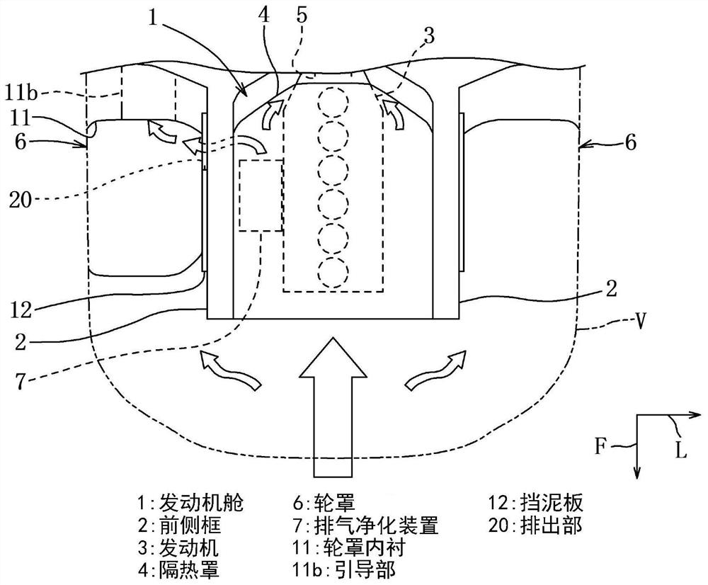
[0057] like figure 1 As shown, an engine compartment 1 is provided at the front side portion of the vehicle V. Hereinafter, the arrow f, the arrow L, the arrow U indicate the front, left, and above of the vehicle. In the engine compartment 1, a multi-cylinder engine 3 (so-called longitudinal engine) arranged in the front-rear direction is housed between a pair of front side frames 2 extending in the front-rear direction of the vehicle V. The engine 3 covers the upper surface, the rear portion, the left side portion, and the portion of the upper surface portion can be opened and closed by the engine cover (hereinafter referred to as the heat shield 4).

[0058] The engine compartment 1 is divided in the vehicle wid...


PUM


Abstract

Provided is an engine compartment heat removal structure capable of promoting heat removal of an engine compartment and suppressing an increase in air resistance when a vehicle is traveling. The engine compartment removal structure for removing heat from an engine compartment is provided with an engine compartment in which an engine in which a cylinder row is arranged in the front-rear direction of a vehicle is housed; a wheel cover which is arranged on the outer side of the engine compartment in the vehicle width direction; an exhaust gas purification device disposed between the engine and the wheel cover; a mudguard which is used for preventing water from entering the engine compartment from the wheel cover; and a wheel cover liner for protecting the inner wall of the wheel cover. The wheel cover is provided with: a discharge part provided to the rear of the mudguard than the exhaust purification device in order to discharge a part of cooling air that cools the exhaust purification device into the wheel cover; and a guide part provided in the wheel cover liner to guide the cooling air discharged into the wheel cover toward the lower side of the vehicle behind the wheel cover.

Description

Technical field [0001] The present invention relates to an engine compartment exhaust configuration of the heat of the engine compartment of the vehicle. Background technique [0002] Since in the past, an engine compartment that accommodates the generating heat is provided in front of the vehicle. The rear of the engine compartment is divided by the engine partition, and the front panel is divided by the front panel on both sides, and the upper portion is divided by the hood. Moreover, the lower side of the front windshield, the front side of the front windshield, the front side of the front windshield, the front side of the front windshield, the front side of the front windshield, the front side of the front windshield. [0003] On the other hand, it is sometimes mainly to cover the engine through the hood of the hood. Further, in order to protect the engine or the like from small stones during the vehicle, the engine or the like and to rectify the air flowing through the vehic...

Claims


Application Information

Patent Timeline
Patent Type & Authority Applications(China)
IPC IPC(8): B62D25/08B60K11/06
CPCB62D25/082B60K11/06F01P2001/005F01P3/20B60R13/0861B60R13/0838B60K11/08F01P11/10
Inventor 山内真二山田翔太齐藤道雄榎本正芳伊川雄希
Owner MAZDA MOTOR CORP
Why Eureka
Try Eureka