Method, device and system for controlling motion of tail end of cantilever crane, medium and engineering machinery

A motion control device and motion control technology, applied in the field of system, control method of boom end motion, medium and engineering machinery, device, can solve the problems of complex operation, unintuitive manipulation of the trajectory movement of the end of the boom, etc., and achieve intuitive operation convenient effect

Active Publication Date: 2021-09-28
ZOOMLION HEAVY IND CO LTD
View PDF6 Cites 4 Cited by
  • Summary
  • Abstract
  • Description
  • Claims
  • Application Information

AI Technical Summary

Problems solved by technology

However, the trajectory movement at the end of the boom often needs to be realized indirectly by a person or a controller by manipulating ea

Method used


Image

  • Method, device and system for controlling motion of tail end of cantilever crane, medium and engineering machinery
  • Method, device and system for controlling motion of tail end of cantilever crane, medium and engineering machinery
  • Method, device and system for controlling motion of tail end of cantilever crane, medium and engineering machinery

Examples


Example Embodiment

[0037] Example 1

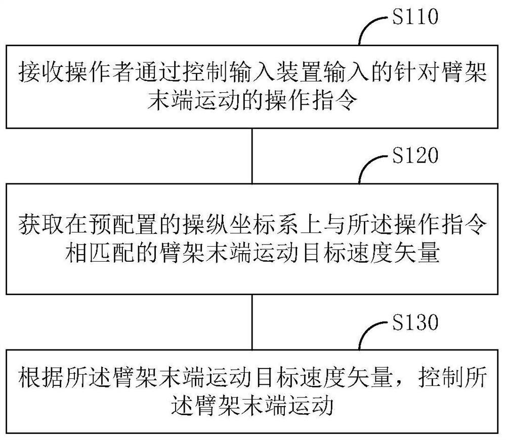
[0038] figure 1 This is a schematic flowchart of the motion control method of the boom end according to the first embodiment of the present invention, wherein the boom is, for example, the boom of a pump truck, and the corresponding boom end is, for example, where the distribution point of the pump truck is located.

[0039] like figure 1 As shown, the motion control method may include steps S110-S120 of the following steps:

[0040] Step S110, receiving an operation instruction for the movement of the end of the boom that is input by the operator through the control input device.

[0041] Step S120, acquiring the boom end moving target velocity vector matching the operation instruction on the preconfigured manipulation coordinate system.

[0042] Step S130: Control the movement of the boom end according to the target velocity vector of the boom end movement.

[0043] For step S110, the operation instruction is used to show how the operator manipulates t...

Example

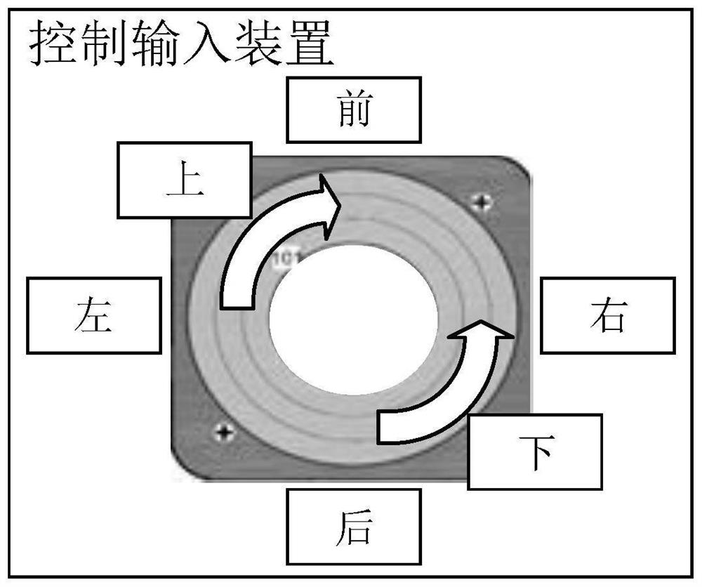
[0048] Example 1: As shown in Figure 2(a), the remote control is configured with a single joystick. By moving the joystick up and down, left and right, and forward and reverse rotations, the three groups of operations of front and rear, left and right, and up and down can be realized respectively. .

Example

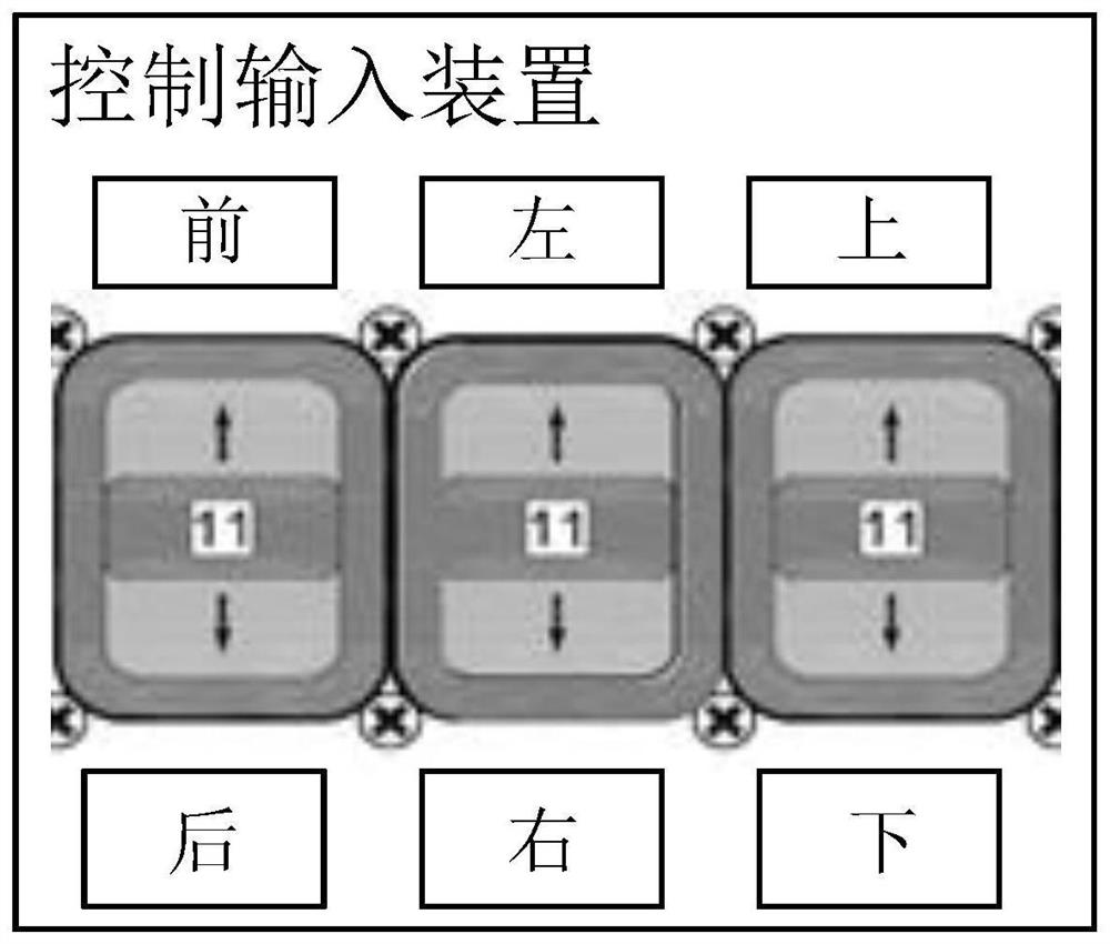
[0049] Example 2: As shown in Figure 2(b), the remote control is configured with three levers, and the down-and-down movements of the three levers correspond to the three groups of directions: front and rear, left and right, and up and down.


PUM


Abstract

The invention relates to the field of mechanical control, and discloses a method, a device and a system for controlling the motion of the tail end of a cantilever crane, a medium and engineering machinery. The motion control method comprises the steps that an operation instruction which is input by an operator through a control input device and aims at motion of the tail end of the cantilever crane is received, and the operation instruction is used for showing the operation-control mode of the operator on the control input device; a cantilever crane tail end motion target velocity vector matched with the operation instruction on a pre-configured operation-control coordinate system is obtained, wherein the operation-control coordinate system is configured to establish correlation between the operation-control mode and cantilever crane tail end motion, and the operation-control coordinate system and the cantilever crane tail end keep a fixed space relation; and the cantilever crane tail end motion is controlled according to the cantilever crane tail end motion target velocity vector. The operation-control coordinate system is designed, and the correlation between the operation-control mode of an operator and the cantilever crane tail end motion is established, so that the operation and control are visual and convenient.

Description

technical field [0001] The present invention relates to the field of mechanical control, in particular, to a control method, device, system, medium and construction machinery for the movement of the end of a boom. Background technique [0002] At present, when a construction machine such as a pump truck is operating, it is generally necessary to operate the boom, so that the end of the boom can be used for material distribution along the material track. However, the trajectory motion of the boom end often requires a person or a controller to indirectly realize by manipulating each section of the boom, which is complicated to operate, and makes it unintuitive to manipulate the trajectory motion of the boom end. SUMMARY OF THE INVENTION [0003] The purpose of the present invention is to provide a control method, device, system, medium and construction machinery for the movement of the end of a boom, which are used to at least partially solve the above technical problems. ...

Claims


Application Information

Patent Timeline
IPC IPC(8): E04G21/04
CPCE04G21/0445E04G21/0463
Inventor 佟祥伟尹君符伟杰曾中炜聂一彪
Owner ZOOMLION HEAVY IND CO LTD
Why Eureka
Try Eureka