Supercharge Your Innovation With Domain-Expert AI Agents!

Active anti-theft electromagnetic lock catch with actuating structure having signal feedback function

An electromagnetic lock and signal technology, applied in non-mechanical transmission-operated locks, electric alarm locks, building locks, etc., can solve the problems of easy misjudgment, hidden safety hazards, and no mechanical structure, and achieve reliable results. , the effect of improving safety

Pending Publication Date: 2021-09-28
WUHAN HANGDA AERO SCI & TECH DEV
View PDF1 Cites 0 Cited by
  • Summary
  • Abstract
  • Description
  • Claims
  • Application Information

AI Technical Summary

Problems solved by technology

[0005] ① Judge whether the electromagnetic lock is unlocked or locked only by whether the feedback voltage or current is within the set threshold range. When the control circuit is disturbed or malfunctions, misjudgment is prone to occur;
[0006] ② There is no feasible mechanical structure, and it is impossible to judge whether the mechanical structure for unlocking or locking is in place;
[0007] ③It cannot be judged whether the lock tongue is inserted into the lock buckle, leaving a potential safety hazard

Method used


Image

  • Active anti-theft electromagnetic lock catch with actuating structure having signal feedback function
  • Active anti-theft electromagnetic lock catch with actuating structure having signal feedback function
  • Active anti-theft electromagnetic lock catch with actuating structure having signal feedback function

Examples


Embodiment Construction

[0067] The implementation of the present invention will be described in detail below in conjunction with the accompanying drawings, but they do not constitute a limitation to the present invention, and are only examples. At the same time, the advantages of the present invention are clearer and easier to understand through the description.

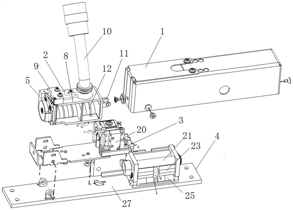
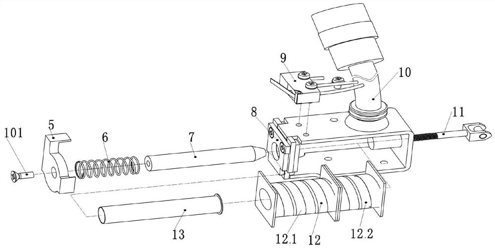
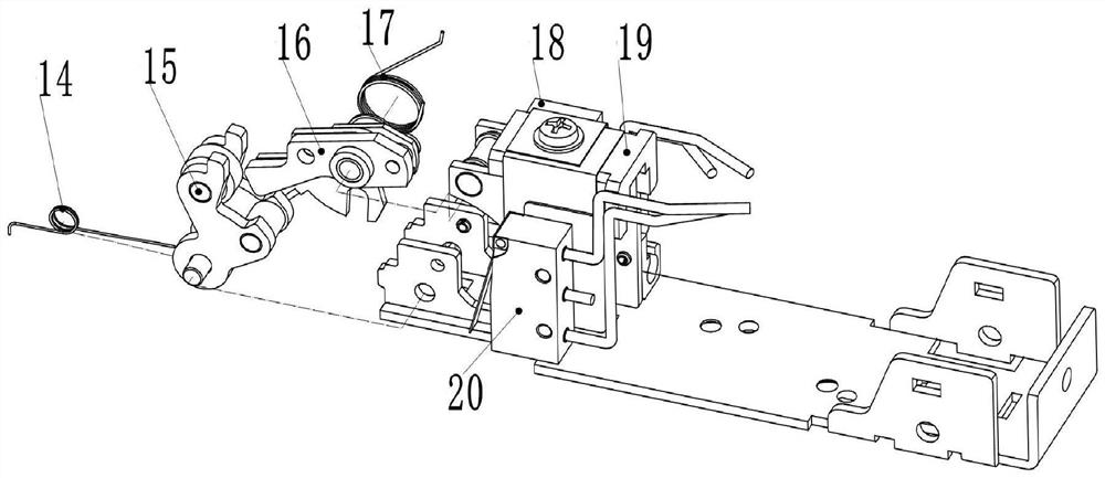
[0068] The present invention generates the on-off signal through the micro switch to give the unlocking and locking signals, can feedback whether the lock tongue is inserted into the lock buckle, and can also judge the function of the electromagnetic lock coil component is normal, which is a combination of three kinds of signal feedback functions electromagnetic lock. The invention is a structural form of an electromagnetic lock installed on a door column, and the invention locks and unlocks through the rotation of the lock. And the mechanical actuating structure in the present invention actually moves to the corresponding position to touc...


PUM


Abstract

The invention discloses an active anti-theft electromagnetic lock catch with an actuating structure having a signal feedback function. The electromagnetic lock catch comprises a lock shell assembly, an electromagnetic transmission assembly, a lock body transmission assembly and a lock seat assembly. The electromagnetic transmission assembly is installed on the lock body transmission assembly through screws. The lock shell assembly and the lock body transmission assembly are both installed on the lock seat assembly. The electromagnetic transmission assembly and the lock body transmission assembly are both located between the lock shell assembly and the lock seat assembly. The electromagnetic transmission assembly comprises a magnet box assembly, a cylindrical spiral spring, an armature, a coil supporting frame assembly, a microswitch I, a cable assembly, an actuating rod assembly, a coil assembly and a copper sleeve. The cable assembly is connected with the microswitch I and the coil assembly in a welded mode. The cable assembly is connected with a microswitch II and a microswitch III in a welded mode. The locking transmission rod assembly, the lock catch and a spring bolt transmission assembly are sequentially arranged from top to bottom. The active anti-theft electromagnetic lock catch with the actuating structure having the signal feedback function has the advantages that the position of the actuating structure can be directly fed back to judge whether the electromagnetic lock is unlocked or locked, and whether the spring bolt extends into the lock catch or not can be fed back.

Description

technical field [0001] The invention relates to the technical field of a mechanical electromagnetic lock, in particular to an active anti-theft electromagnetic lock with an actuating structure and signal feedback. Background technique [0002] At present, most of the existing electromagnetic lock structures are electromagnetic door locks (installed on the upper part of the door), and there are few applications of electromagnetic locks (installed on the inner part of the door frame). Due to the different installation positions of the electromagnetic door lock and the electromagnetic lock catch, there is a big difference in the actuating structure. The electromagnetic door lock focuses on the action of the bolt, while the electromagnetic lock focuses on the action of the lock. In addition, the existing electromagnetic locks have less monitoring of the actuating structure, and cannot quickly determine whether the electromagnetic lock is unlocked, locked, or faulty, and cannot m...

Claims


Application Information

Patent Timeline
IPC IPC(8): E05B47/06E05B15/00E05B15/10E05B45/06
CPCE05B47/0001E05B47/0002E05B47/0607E05B15/00E05B15/10E05B45/06E05B2047/0068E05B2047/0069E05B2045/065
Inventor 刘滨阳肖紫圣陈超群李伟明
Owner WUHAN HANGDA AERO SCI & TECH DEV
Features
  • R&D
  • Intellectual Property
  • Life Sciences
  • Materials
  • Tech Scout
  • Unparalleled Data Quality
  • Higher Quality Content
  • 60% Fewer Hallucinations
Learn More