Packer capable of protecting rubber sleeve for oil field water injection well

A technology of oilfield water injection and packer, which is applied in the direction of sealing/packing, flushing wellbore, wellbore/well parts, etc., and can solve the problems of reducing the service life of the rubber cartridge and not being able to protect the rubber cartridge

Active Publication Date: 2021-09-28
扬州睿德石油机械有限公司
View PDF6 Cites 0 Cited by
  • Summary
  • Abstract
  • Description
  • Claims
  • Application Information

AI Technical Summary

Problems solved by technology

[0006] In order to overcome the above-mentioned patents, the rubber sleeve cannot be protected during the process of placing and taking out the packer. When the rubber sleeve moves in the tubing and oil and gas well casing, it is easy to contact and rub with small stones, thereby reducing the use of the rubber sleeve. The shortcoming of service life, the technical problem to be solved by the present invention is to provide a kind of oil field water injection well that can protect the rubber sleeve during the process of placing and taking out the packer, thereby improving the service life of the rubber sleeve. Packer

Method used


Image

  • Packer capable of protecting rubber sleeve for oil field water injection well
  • Packer capable of protecting rubber sleeve for oil field water injection well
  • Packer capable of protecting rubber sleeve for oil field water injection well

Examples


Embodiment 1

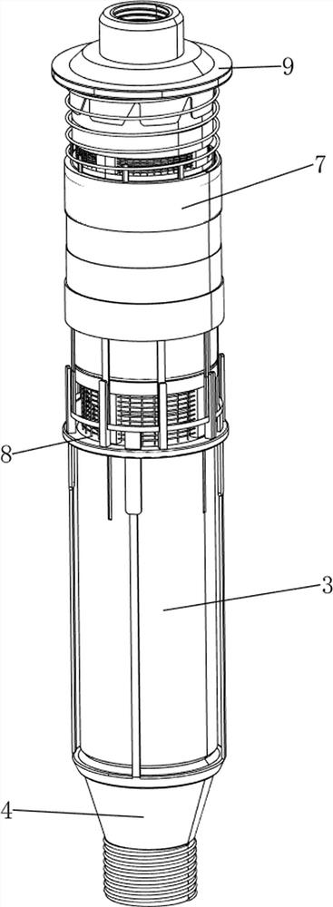
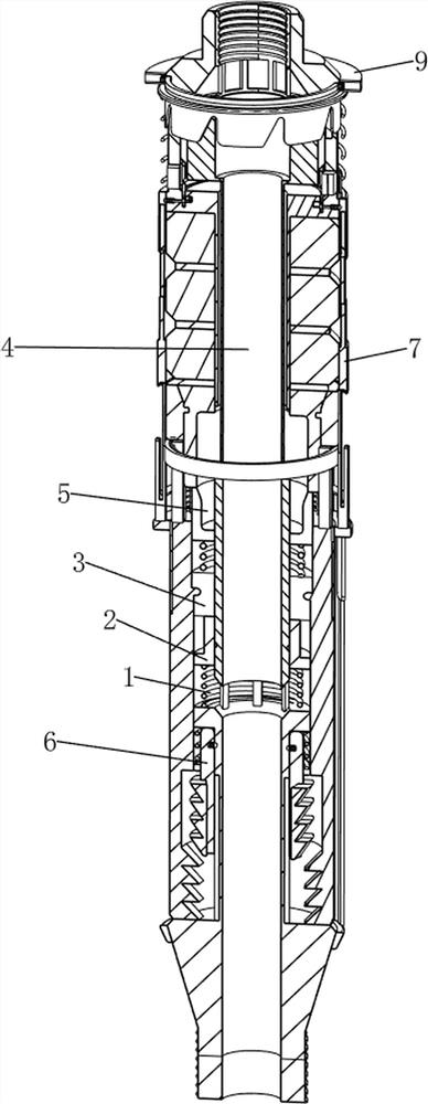
[0048] A packer for oilfield water injection wells that can protect rubber cartridges, such as figure 1 with figure 2 As shown, it includes a first return spring 1, a movable block 2, a setting mechanism 3, an unsealing mechanism 4 and a valve mechanism 5, and also includes a pressure relief mechanism 6 and a protection mechanism 7, and the unsealing mechanism 4 is provided with a setting mechanism. Mechanism 3, the first return spring 1 and the pressure relief mechanism 6, the top of the first return spring 1 is connected with a movable block 2, a valve mechanism 5 is arranged between the unsealing mechanism 4 and the setting mechanism 3, the setting mechanism 3 and the unsealing mechanism A protective mechanism 7 is provided between the mechanisms 4 .

[0049] When the packer needs to be used, first install the packer through the unsealing mechanism 4, after installation, input the high-pressure liquid into the unsealing mechanism 4, and input the high-pressure liquid in t...

Embodiment 2

[0060] On the basis of Example 1, such as Figure 20 with Figure 21 As shown, a filter mechanism 8 is also included, and the filter mechanism 8 includes a brush plate 81, a first filter screen 82 and a second filter screen 83, and a brush plate 81 is connected between the upper parts of the plurality of support plates 74, and each adjacent two The first filter screen 82 is connected between the second connecting block 33 of the first block, and the brush plate 81 is slidably matched with the second connecting block 33. The brush plate 81 brushes the impurities on the first filter screen 82, and every adjacent two pieces A second filter net 83 is connected between the fixing blocks 43 .

[0061] In the process of pouring in and gushing out, the water plays the role of filtering through the first filter screen 82 and the second filter screen 83. When the second connecting block 33 moves upward, it drives the second filter screen 83 to move upward together, and the second filte...

Embodiment 3

[0063] On the basis of Example 2, such as figure 2 , Figure 22 with Figure 23 As shown, it also includes a blocking mechanism 9, the blocking mechanism 9 includes a first blocking plate 91, a third common spring 92, a rotating cylinder 93, a third block 94, a second blocking plate 95 and a push rod 96, and the upper connector The upper part of 41 is connected with a first shielding plate 91, and the upper part of the outer arc surface of the upper connector 41 is connected with multiple groups of third ordinary springs 92 evenly spaced along the circumferential direction, and the third ordinary springs 92 of each group are two sets, and the two of each group A second shielding plate 95 is connected between the third common springs 92, and the second shielding plate 95 is slidingly matched with the first shielding plate 91. The upper part of the upper connector 41 is rotatably connected with a drum 93, and the drum 93 is positioned at the first shielding plate. Below the p...


PUM


Abstract

The invention relates to the technical field of packers, in particular to a packer capable of protecting a rubber sleeve for an oil field water injection well with the advantages that in the process of placing and taking out the packer, the rubber sleeve can be protected, so that the service life of the rubber sleeve is prolonged. The packer comprises a first reset spring, a movable block, a setting mechanism, an unsetting mechanism, a valve mechanism and the like, wherein the setting mechanism, the first reset spring and a pressure relief mechanism are arranged on the unsealing mechanism; the movable block is connected to the top of the first reset spring; a valve mechanism is arranged between the unsealing mechanism and the setting mechanism; and a protection mechanism is arranged between the setting mechanism and the unsealing mechanism. An oil pipe and an oil and gas well casing pipe are set through deformation of a setting rubber sleeve in the setting mechanism, so that the setting effect is achieved.

Description

technical field [0001] The invention relates to the technical field of packers, in particular to a packer for oil field water injection wells capable of protecting rubber cylinders. Background technique [0002] Petroleum is an important non-renewable resource in modern society. The way to exploit oil now is usually through oil fields. In the process of exploitation, packers are usually used to seal oil pipes and oil and gas well casings. Separation and well cleaning operations. [0003] After retrieval, the authorized patent publication number is CN206830122U, which discloses a water injection packer, including: an inner tube, a sealing mechanism sleeved outside the inner tube, a first working cylinder, a second working cylinder and a setting mechanism: A water injection hole is provided on the wall of the inner tube; a sleeve that can reciprocate along the axial direction of the inner tube is provided in the inner tube, and a water injection hole is provided on the sleeve...

Claims


Application Information

Patent Timeline
Patent Type & Authority Applications(China)
IPC IPC(8): E21B33/127E21B43/20E21B21/10B01D33/01B01D33/35B01D33/46
CPCE21B33/127E21B43/20E21B21/10B01D33/0108B01D33/35B01D33/461
Inventor 李祥宝
Owner 扬州睿德石油机械有限公司
Why Eureka
Try Eureka