A method for forming a stator core
A stator core and forming method technology, applied in the manufacture of stator/rotor bodies, electromechanical devices, electrical components, etc., can solve the problems of low utilization rate of copper wires, reduction of assembly inner holes, etc., increase assembly inner holes, improve copper The effect of line utilization
- Summary
- Abstract
- Description
- Claims
- Application Information
AI Technical Summary
Problems solved by technology
Method used
Image
Examples
Embodiment 1
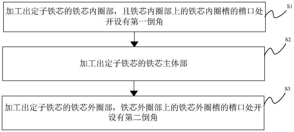
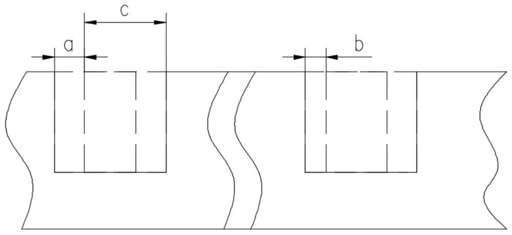
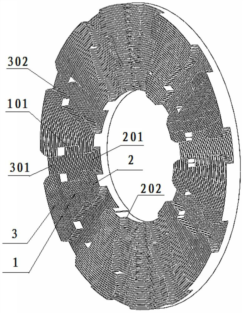
[0043] see Figure 1-5 , is a flow chart of the stator core forming method provided by the present invention.
[0044] The invention discloses a stator core forming method, comprising the following steps:
[0045] Step S1 : Process the inner core ring part 2 of the stator core, and a first chamfer 202 is provided at the opening of the inner ring groove 201 on the inner ring part 2 of the iron core.
[0046] The inner ring portion 2 of the iron core can be formed by die pressing, or by stamping and rolling of a silicon steel sheet. A plurality of iron core inner ring slots 201 are opened on the processed iron core inner ring portion 2 along the radial direction of the iron core inner ring portion 2 .
[0047] The slots 201 of the inner ring of the iron core are evenly distributed on the inner ring portion 2 of the iron core.
[0048] The first chamfer 202 is provided at the notch at the end of the iron core inner ring groove 201 close to its axis. The first chamfer 202 may ...
Embodiment 2
[0059]In yet another embodiment of the present invention, the stator core forming method in this embodiment is similar to the stator core forming method in the first embodiment, and the similarities will not be repeated, and only the differences will be introduced.
[0060] In this embodiment, the present invention specifically discloses that the stator core is integrally formed by punching and rolling silicon steel sheets.
[0061] Wherein, processing the inner ring portion 2 of the iron core specifically includes the following steps:
[0062] S11: According to the thickness of the silicon steel sheet, combined with the groove width of the inner ring groove 201 of the iron core and the size of the first chamfer 202, calculate the first feeding amount of the silicon steel sheet when punching dies with different turns.
[0063] The first chamfer 202 may be a rounded corner or a chamfer of other shapes.
[0064] S12: Die the silicon steel sheet according to the calculated first...
Embodiment 3
[0095] In the third embodiment of the present invention, the stator core forming method in this embodiment is similar to the stator core forming method in the first embodiment, and the similarities will not be repeated, and only the differences will be introduced.
[0096] In this embodiment, it is disclosed that the inner ring portion 2 of the processed iron core includes:
[0097] S13: The main body of the inner ring of the iron core is made by molding, and the inner ring groove 201 of the iron core is opened on the main body of the inner ring of the iron core.
[0098] The molded material is specifically a soft magnetic material, and it should be noted that it may also be other magnetic materials.
[0099] S14: A first chamfer 202 is provided at the notch of the core inner ring groove 201 of the iron core inner ring main body to form the iron core inner ring part 2 .
[0100] The first chamfer 202 may be a rounded corner or a chamfer of other shapes.
[0101] Further, the...
PUM
 Abstract
Description
Claims
Application Information
 - R&D
- Intellectual Property
- Life Sciences
- Materials
- Tech Scout
- Unparalleled Data Quality
- Higher Quality Content
- 60% Fewer Hallucinations
Browse by: Latest US Patents, China's latest patents, Technical Efficacy Thesaurus, Application Domain, Technology Topic, Popular Technical Reports.
© 2025 PatSnap. All rights reserved.Legal|Privacy policy|Modern Slavery Act Transparency Statement|Sitemap|About US| Contact US: help@patsnap.com


