
Heat energy recovery and environmental protection oil fume treatment device

A technology for oil fume treatment and heat recovery, which is applied in waste heat treatment, heat exchanger type, preheating, etc. It can solve the problems of filter layer clogging, high heat in the flue gas that is not effectively collected and utilized, and affects the treatment effect, etc., to achieve Improve collection efficiency, maintain continuous and stable operation, and have good environmental protection

Active Publication Date: 2022-02-25
温州宪江防腐设备有限公司
View PDF8 Cites 0 Cited by
  • Summary
  • Abstract
  • Description
  • Claims
  • Application Information

AI Technical Summary

Problems solved by technology

[0007] The purpose of the present invention is to provide heat energy recovery and environmental protection oil fume treatment device to solve the technical problems in the prior art that the high heat part in the flue gas is not effectively collected and utilized, and the oil in the flue gas easily blocks the filter layer and affects the treatment effect

Method used


Image

  • Heat energy recovery and environmental protection oil fume treatment device
  • Heat energy recovery and environmental protection oil fume treatment device
  • Heat energy recovery and environmental protection oil fume treatment device

Examples


Embodiment Construction

[0034] The technical solutions of the present invention will be clearly and completely described below in conjunction with the accompanying drawings. Apparently, the described embodiments are some of the embodiments of the present invention, but not all of them.

[0035] The components of the embodiments of the invention generally described and shown in the figures herein may be arranged and designed in a variety of different configurations. Accordingly, the following detailed description of the embodiments of the invention provided in the accompanying drawings is not intended to limit the scope of the claimed invention, but merely represents selected embodiments of the invention.

[0036]Based on the embodiments of the present invention, all other embodiments obtained by persons of ordinary skill in the art without making creative efforts belong to the protection scope of the present invention.

[0037] In the description of the present invention, it should be noted that the ...


PUM


Abstract

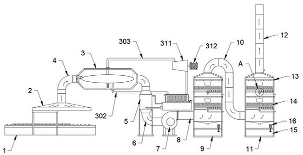
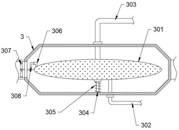
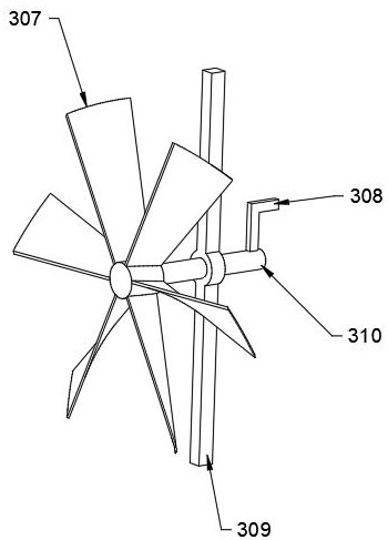
The invention discloses a thermal energy recovery and environment-friendly oil fume treatment device, which relates to the technical field of annealing furnace flue gas treatment, and includes an annealing furnace, a heat exchange tube, a cooler, a fan, a spray tower 1 and a spray tower 2, and above the annealing furnace A suction hood is provided, the inner wall of the heat exchange tube is provided with a steam generating mechanism, a plurality of said shunt pipes are sleeved on the inner wall of the shunt outlet, and the outer wall of the shunt sleeve is equipped with a heat dissipation assembly, and the outer wall of the cooler The socket has a water cooling mechanism. The present invention adds water to the inner wall of the ellipsoid water tank in advance through the return pipe, and the flue gas can heat the water on the inner wall of the ellipsoid water tank until it boils, and the high-pressure steam generated during boiling is supplied to the steam turbine through the steam pipe to drive the blades to rotate and drive the generator to generate electricity , so that the high-heat part in the flue gas is recovered first, and then enters the subsequent heat exchange device to realize the graded utilization of heat in the flue gas, realize the utilization of high temperature in the flue gas, good environmental protection, and improve the efficiency of heat collection .

Description

technical field [0001] The invention relates to the technical field of annealing furnace flue gas treatment, in particular to a thermal energy recovery and environment-friendly oil fume treatment device. Background technique [0002] Enterprises produce oily waste gas and non-methane total hydrocarbons in the production process of stainless steel annealing furnace. Because the waste gas has a certain impact on the surrounding environment and the personal safety of workers, in order to further do a good job in environmental protection and avoid affecting the factory area and the surrounding atmospheric environment, it is necessary To process the flue gas, it is also necessary to recover the heat energy in the flue gas. [0003] For the actual demand of flue gas treatment in the production of annealing furnace. [0004] (1) The Chinese utility model patent with the publication number CN211339632U ​​discloses a waste gas heat exchange device for a stainless steel belt annealin...

Claims


Application Information

Patent Timeline
Patent Type & Authority Patents(China)
IPC IPC(8): F27D17/00F22B1/18F22D11/06F23J15/06F28C3/06F28F25/06F28F25/08F01D15/10
CPCF27D17/004F27D17/008F22B1/18F22D11/06F23J15/06F28C3/06F28F25/06F28F25/08F01D15/10Y02E20/30Y02P10/25Y02P10/143
Inventor 邵宪江邵何蓓沈宇
Owner 温州宪江防腐设备有限公司
Learn More