Thermal insulation supporting structure for hoisting part of low-temperature pipeline

A technology for supporting structures and hoisting parts, applied in the direction of pipeline protection, pipeline protection through heat insulation, heat preservation, etc., can solve problems such as damage to heat insulation materials, and achieve the effect of preventing damage

Active Publication Date: 2021-09-28
重庆海科保温材料有限公司
View PDF14 Cites 0 Cited by
  • Summary
  • Abstract
  • Description
  • Claims
  • Application Information

AI Technical Summary

Problems solved by technology

[0002] In production activities, pipelines are mainly used for the transportation of fluid materials. They can be divided into normal temperature, high temperature and low temperature according to temperature alone. Normal temperature pipelines usually only need anti-corrosion treatment on their surfaces, while high-temperature and low-temperature pipelines need to be treated on the basis of anti-corrosion. Make heat insulation materials to prevent heat loss and accidental burns in high-temperature pipes, and pressure changes in the internal medium caused by the contact between low-temperature pipes and external connections; the usual practice is to coat high-temperature pipes and low-temperature pipes with glass fiber and other heat-insulating materials. However, for the hoisting pipeline passing through high altitude, it is necessary to use fixed structures such as lifting rings to lift the pipeline during the hoisting process, and the insulation material will squeeze between the coated heat insulation material and the lifting ring due to its own weight. Combined with the vibration generated by the fluid flow in the pipeline, the heat insulation material that is exposed to the stressed parts of the pipeline and the lifting ring under long-term action will be squeezed and rubbed and damaged

Method used


Image

  • Thermal insulation supporting structure for hoisting part of low-temperature pipeline
  • Thermal insulation supporting structure for hoisting part of low-temperature pipeline
  • Thermal insulation supporting structure for hoisting part of low-temperature pipeline

Examples


Embodiment Construction

[0027] The principles and features of the present invention are described below in conjunction with the accompanying drawings, and the examples given are only used to explain the present invention, and are not intended to limit the scope of the present invention.

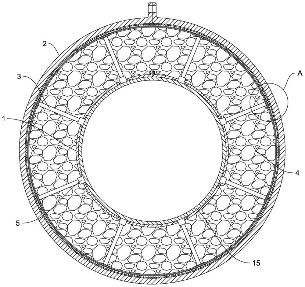
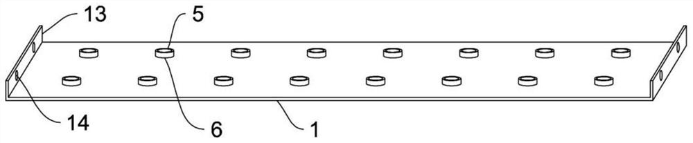
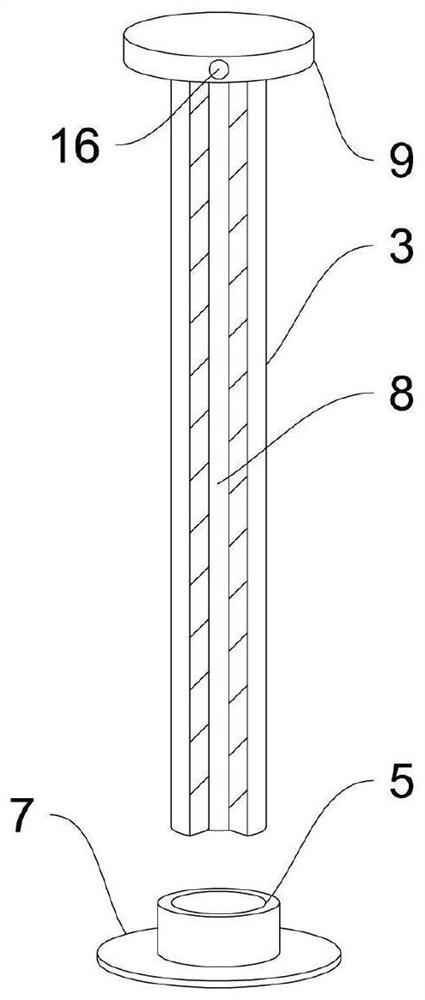
[0028] Such as figure 1 , figure 2 , image 3 , Figure 4 As shown, a heat insulation support structure for the hoisting part of a low-temperature pipeline 15 includes a fixing belt 1, a hoisting ring 2 and a plurality of support rods 3, and the fixing belt 1 is wrapped around the hoisting part of the pipeline 15 to form a ring structure. The hoisting ring 2 is set outside the fixing belt 1, and a heat insulation layer 4 is filled between the hoisting ring 2 and the fixing belt 1, and one end of several support rods 3 penetrates the heat insulation layer 4 and is connected with the outer wall of the fixing belt 1, and Evenly distributed in a radial structure, the other end of the support rod 3 is fixed against t...


PUM


Abstract

The invention relates to a thermal insulation supporting structure for a hoisting part of a low-temperature pipeline, which comprises a fixing belt, a hoisting ring and a plurality of supporting rods, wherein the fixing belt wraps the hoisting part of the pipeline to form an annular structure, the hoisting ring is arranged outside the fixing belt in a sleeving mode, the space between the hoisting ring and the fixing belt is filled with a thermal insulation layer, one ends of the plurality of supporting rods penetrate through the thermal insulation layer to be connected with the outer wall of the fixing belt and are evenly distributed to be of a radial structure, and the other ends of the supporting rods abut against and are fixed to the inner wall of the hoisting ring. According to the technical scheme, the thermal insulation layer arranged between the fixing belt and the hoisting ring can be prevented from being extruded, the protection effect on the thermal insulation layer is achieved, and the thermal insulation layer is prevented from being damaged due to extrusion friction between the lower portion of the pipeline and the hoisting ring.

Description

technical field [0001] The invention relates to the field of pipeline insulation structures, in particular to a heat insulation support structure for the hoisting part of a low-temperature pipeline. Background technique [0002] In production activities, pipelines are mainly used for the transportation of fluid materials. They can be divided into normal temperature, high temperature and low temperature according to temperature alone. Normal temperature pipelines usually only need anti-corrosion treatment on their surfaces, while high-temperature and low-temperature pipelines need to be treated on the basis of anti-corrosion. Make heat insulation materials to prevent heat loss and accidental burns in high-temperature pipes, and pressure changes in the internal medium caused by the contact between low-temperature pipes and external connections; the usual practice is to coat high-temperature pipes and low-temperature pipes with glass fiber and other heat-insulating materials. ...

Claims


Application Information

Patent Timeline
Patent Type & Authority Applications(China)
IPC IPC(8): F16L59/12F16L59/135
CPCF16L59/123F16L59/135F16L59/12
Inventor 劳瑜
Owner 重庆海科保温材料有限公司
Why Eureka
Try Eureka