A distance measuring device for geological exploration

A technology for measuring distance and geological exploration, applied in the direction of measuring devices, instruments, machines/stands, etc., can solve problems such as troubles, and achieve the effect of increasing the stability of placement

Active Publication Date: 2021-11-12
南通市金润市政工程有限公司
View PDF10 Cites 0 Cited by
  • Summary
  • Abstract
  • Description
  • Claims
  • Application Information

AI Technical Summary

Problems solved by technology

[0002] Conventional distance measuring instruments are mainly supported by ordinary tripods during use. When the user transports it to the target point, it is necessary to adjust each foot according to the ground to ensure the balance of the device. Single adjustment of the supporting feet It is more troublesome and needs to be adjusted repeatedly, so there is an urgent need for a solution that can alleviate the above problems

Method used


Image

  • A distance measuring device for geological exploration
  • A distance measuring device for geological exploration
  • A distance measuring device for geological exploration

Examples


Embodiment 1

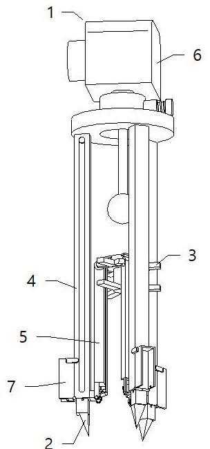
[0031] see figure 1 , a measuring distance device for geological exploration, comprising a measuring instrument 1, the measuring instrument 1 includes a balance main body 6, the measuring instrument 1 also includes an adaptive support foot 2, an operating main body 3, a sleeve 4, a guiding main body 5 and a protecting main body 7, The self-adaptive support foot 2 and the sleeve 4 are slidably installed together, the operating body 3 is connected with the self-adaptive support foot 2, the upper end of the sleeve 4 is rotationally connected with the balance main body 6, and the guiding body 5 is connected with the operation body 3 and the sleeve. The sleeve 4 is rotatably connected, the protective body 7 is rotatably connected with the sleeve 4, and the self-adaptive support foot 2 is locked together with the sleeve 4; during use, the sleeve 4 is unfolded first, and the guide body 5 is used to restrict the sleeve 4, and then hold up the lower part of the balance body 6 with one ...

Embodiment 2

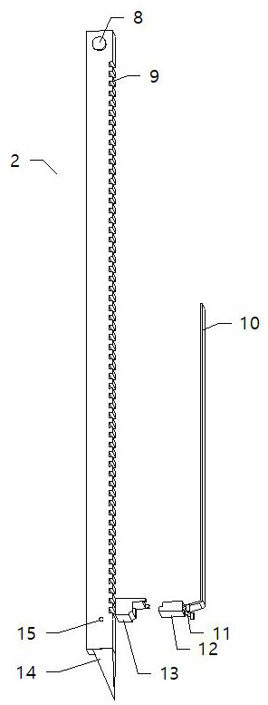
[0033]see figure 2 , the self-adaptive support foot 2 includes a limit block 8, a first slide bar 9, a tie bar 10, a shrapnel 11, a first slide bolt 12, a first guide sleeve 13 and a bayonet 15, and the limit block 8 is fixedly connected to the first The upper outer end of the slide bar 9 and the upper end of the pull bar 10 are fixedly connected with the operating body 3, the lower end of the pull bar 10 is fixedly connected with the first slide bolt 12, and one end of the shrapnel 11 slides and squeezes on the first slide bolt. 12, the shrapnel 11 is fixedly connected with the first guide sleeve 13, the first guide sleeve 13 is fixedly connected to the lower outer end of the guide body 5, and the bayonet 15 is provided at the lower outer end of the first slide bar 9, and the pull The bar 10 is in rolling contact with the guide body 5, the first slide bolt 12 is clamped and matched with the first slide rod 9, and the first slide bolt 12 is slidably installed on the inner end...

Embodiment 3

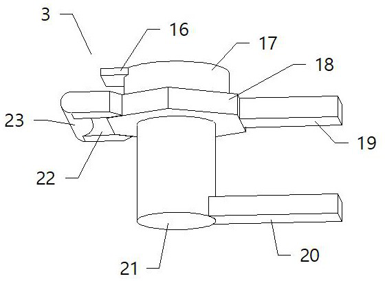
[0036] see image 3 , the operating body 3 includes a first connection block 16, a stopper 17, a second guide sleeve 18, a first knob 19, a second knob 20, a second slide bar 21, a second connection block 22 and a fixed shaft 23, the second One end of a connection block 16 is fixedly connected with the stopper 17, the other end of the first connection block 16 is fixedly connected with the self-adaptive support foot 2, the stopper 17 is in sliding contact with the second guide sleeve 18, and the stopper 17 The lower end is fixedly connected with the upper end of the second slide bar 21, the second guide sleeve 18 is slidably sleeved on the outer end of the second slide bar 21, the first knob 19 is fixedly connected with the second guide sleeve 18, and the second guide sleeve 18 is fixedly connected together. The knob 20 is fixedly connected with the second slide bar 21, the second connecting block 22 is symmetrically fixedly connected to the outer end of the second guide sleev...


PUM


Abstract

The invention discloses a measuring distance device for geological exploration, which includes a measuring instrument, the measuring instrument includes a balance main body, and the measuring instrument also includes an adaptive support foot, an operating main body, a sleeve, a guiding main body and a protective main body. The self-adaptive support foot and the sleeve are slidably installed together, the operating body is connected with the self-adaptive support foot, the upper end of the sleeve is rotatably connected with the balance main body, and the guiding body is rotatably connected with the operation body and the sleeve connected, the protective body is rotatably connected with the sleeve, the adaptive support foot is locked with the sleeve, and the adaptive support foot includes a limit block, a first slide bar, a pull bar, a shrapnel, A slide bolt, a first guide sleeve and a bayonet socket, the limit block is fixedly connected to the upper outer end of the first slide bar. The invention relates to the technical field of geological detection equipment, which is convenient for users to quickly adjust and use, and better meets the needs of use.

Description

technical field [0001] The invention relates to the technical field of geological detection equipment, in particular to a measuring distance device for geological detection. Background technique [0002] Conventional distance measuring instruments are mainly supported by ordinary tripods during use. When the user transports it to the target point, it is necessary to adjust each foot according to the ground to ensure the balance of the device. Single adjustment of the supporting feet It is more troublesome and needs repeated adjustments, so a solution that can alleviate the above problems is urgently needed. Contents of the invention [0003] The object of the present invention is to provide a distance measuring device for geological exploration, so as to solve the problems raised in the above-mentioned background technology. [0004] In order to achieve the above object, the present invention provides the following technical solutions: a distance measuring device for geol...

Claims


Application Information

Patent Timeline
Patent Type & Authority Patents(China)
IPC IPC(8): F16M11/04F16M11/14F16M11/16F16M11/34F16M7/00G01B21/16
CPCF16M11/04F16M11/14F16M11/16F16M11/34F16M7/00G01B21/16
Inventor 金岳
Owner 南通市金润市政工程有限公司
Why Eureka
Try Eureka