Medullary plug including an external shield and an internal valve

a technology of internal valve and external shield, applied in the field of medical devices, can solve the problems of reducing the time required for a hip replacement procedure, and reducing the cost of the procedur

Inactive Publication Date: 2003-01-14
HAJIANPOUR MOHAMMED ALI
View PDF33 Cites 37 Cited by
  • Summary
  • Abstract
  • Description
  • Claims
  • Application Information

AI Technical Summary

Problems solved by technology

Such materials, which have elastic properties allowing substantial elongation, are subject to cutting and puncturing due to bone splinters and sharp edges in a channel cut into bone, as the plug is moved into position within the channel.
Furthermore, the use of an internal valve associated with a needle for injecting a fluid complicates the manufacture of the inflatable bone plug.
Also, the separate formation of a bone plug from cement and subsequent removal of the conduit and inflatable body to allow insertion of the prosthesis may lengthen the time required for a hip replacement procedure.
However, this type of bone cement plug, having a finite number, such as two, mechanically coupled legs to expand, cannot have the flexibility of a system using an inflatable plug in terms of forming a proper seal within a bone channel which may not be round and smooth, and which varies locally in radius.
However, the expansion of the cement restrictor is limited to the transition between the first stable state and the second stable state, together with elastic and plastic deformation of the material.
This method thus does not offer the kind of flexibility of a system with an inflatable body in expansion to meet varying conditions within the bone channel.
Furthermore, the time required to apply liquids at different temperatures to make the transitionable body perform as desired may increase the time required for hip replacement surgery.
Therefore, such systems cannot compensate for such conditions to the extent possible with systems including inflatable bodies.

Method used


Image

  • Medullary plug including an external shield and an internal valve
  • Medullary plug including an external shield and an internal valve
  • Medullary plug including an external shield and an internal valve

Examples


Embodiment Construction

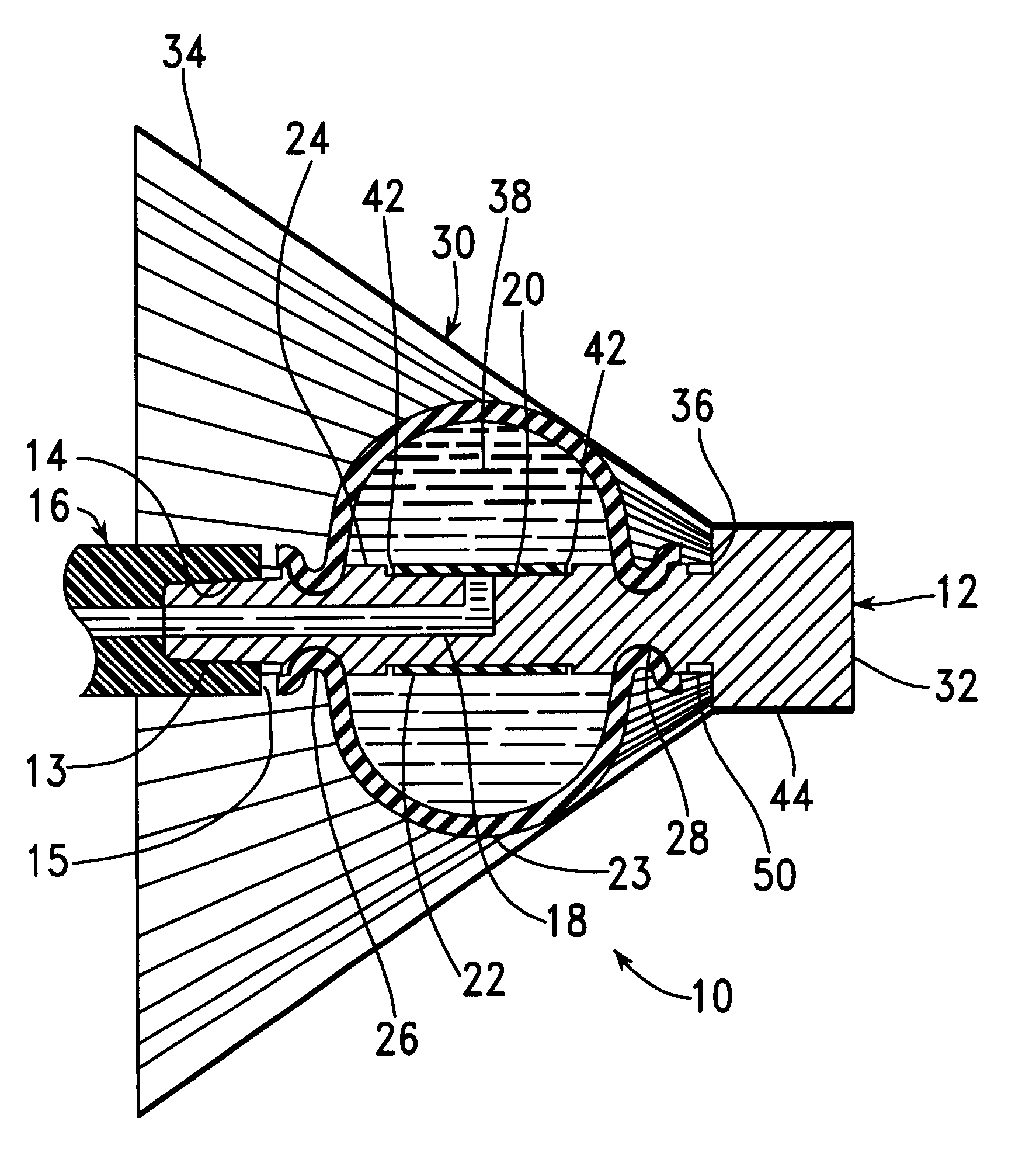
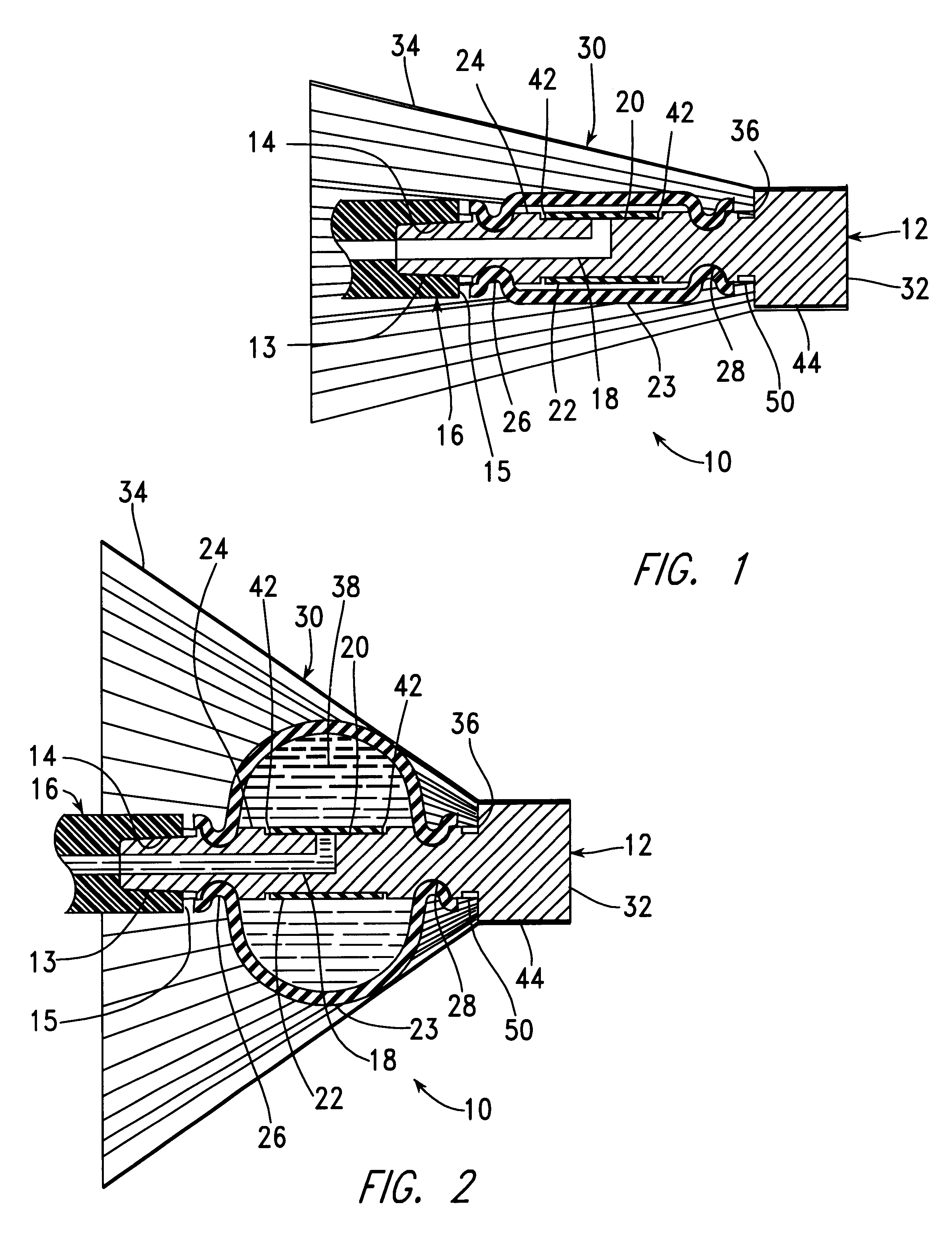
FIG. 1 is a longitudinal cross-sectional view of a bone plug, generally indicated as 10, made in accordance with the present invention. The bone plug 10 includes a generally cylindrical core 12 having a tapered proximal end 13 which is removably attached to a mating tapered hole 14 at a distal end 15 of an insertion device, generally indicated as 16. The core 12 includes an "L"-shaped internal passage 18, extending between the tapered proximal end 13 and a cylindrical surface 20 extending under an elastomeric valve sleeve 22. The core 12 is preferably composed of a molded thermoplastic material such as acetal or high-density polyethylene. A generally cylindrical inflatable elastomeric sleeve 23 extends along a central portion 24 of the core 12, being held in place by internal ridges 26, which extend within grooves 28 in the core 12. The grooves 28 extend around the circumference of the core 12. The internal ridges 26 may also be attached by means of an adhesive within the grooves 28...


PUM


Abstract

A plug for stopping the flow of bone cement in a channel within bone, such as the intramedullary bone canal or a previously prepared channel, includes an elastomeric inflatable structure protected from bone fragments and sharp edges by a shield extending around distal and peripheral sides of the inflatable structure. This inflatable structure is preferably formed as a sleeve extending around a core. The shield includes a distal end fastened to the core and a flexible portion expandable with inflation of the inflatable structure. The core is also removably connected to an insertion tool, with passageways in the insertion tool and in the core being used to insert a fluid into the inflatable structure. A valve extends as a sleeve around the core, and over the passageway, allowing fluid to flow into the inflatable structure, but preventing it from flowing out of the inflatable structure.

Description

BACKGROUND INFORMATION1. Field of InventionThis invention relates to medical apparatus for use in the implantation of a joint prosthesis to the end of a bone and, more particularly, to a plug for stopping the flow of bone cement, used in the attachment of a prosthesis, at a predetermined point within the intramedullary bone channel.3. Description of the Related ArtA number of U.S. Patents describe apparatus for plugging the open end of an intramedullary bone canal to restrict the flow of bone cement during the insertion of bone cement, particularly during the pressurized injection of such a cement during an operative procedure involving the fixation of the stem of an artificial joint prosthesis to the end of a bone such as in the fixation of a hip joint prosthesis to the proximal femur.For example, U.S. Pat. No. 4,697,584 describes an inflatable bone plug which is inflated with a fluid capable of escaping from the plug within a relatively short period of time after the bone cement h...

Claims


Application Information

Patent Timeline
Patent Type & Authority Patents(United States)
IPC IPC(8): A61F2/30A61F2/46A61B19/00A61F2/00A61F2/36
CPCA61F2/30723A61F2/4614A61B19/54A61F2/3676A61F2002/30069A61F2002/4627A61F2002/3021A61F2002/30217A61F2002/4631A61F2230/0067A61F2250/0098A61F2002/3008A61B90/39
Inventor HAJIANPOUR, MOHAMMED ALI
Owner HAJIANPOUR MOHAMMED ALI
Why Eureka
Try Eureka