Signature device for large-amount electronic payment

An electronic payment and signature device technology, applied in the direction of electronic digital data processing, data processing input/output process, instruments, etc., can solve the problems of reduced comfort and mutual entanglement of signatures, so as to improve operating comfort and avoid shaking back and forth , Reduce the effect of rotational resistance

Inactive Publication Date: 2021-09-28
ZHEJIANG VOCATIONAL COLLEGE OF COMMERCE
View PDF9 Cites 0 Cited by
  • Summary
  • Abstract
  • Description
  • Claims
  • Application Information

AI Technical Summary

Problems solved by technology

[0002] In order to prevent the electronic pen from being lost during the use of conventional electronic pens, an elastic thread is usually connected to the upper end of the electronic pen. Since the elastic thread itself needs length, it is easy to entangle with each other after being placed on the table, and the upper end of the electronic pen is subject to certain pressure when signing. Pull force, resulting in reduced signature comfort, so a solution that can alleviate the above problems is urgently needed

Method used


Image

  • Signature device for large-amount electronic payment
  • Signature device for large-amount electronic payment
  • Signature device for large-amount electronic payment

Examples


Embodiment 1

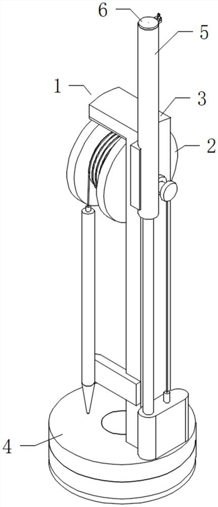
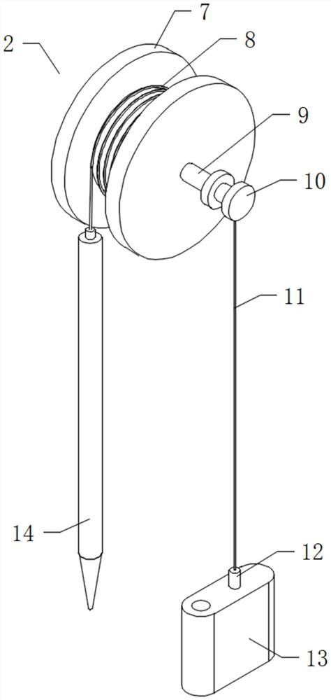
[0026] see Figure 1-2 , an embodiment provided by the present invention: a signature device for large-amount electronic payment, including an electronic pen restraint mechanism 1, the electronic pen restraint mechanism 1 includes an electronic pen 14, and the electronic pen restraint mechanism 1 also includes a retractable main body 2 , the support frame 3 and the swivel seat 4, the lower end of the support frame 3 is fixedly connected to the upper end of the swivel seat 4, and the retractable main body 2 and the support frame 3 are rotated and installed together; 8. The first rotating shaft 9, the second winding roller 10, the stay cord 11 and the weight 13, the upper end of the electronic pen 14 is fixedly connected with the lower end of the binding wire 8, and the other end of the binding wire 8 is connected with the first winding roller. 7 are fixedly installed together, and the binding wire 8 is wound on the inner end of the first winding roll 7, and one end of the first...

Embodiment 2

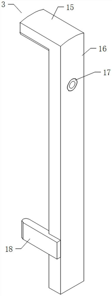
[0028] see Figure 3-6 , an embodiment provided by the present invention: the support frame 3 includes a support column 16, the lower end of the support column 16 is fixedly installed with the swivel base 4, the first rotating shaft 9 runs through the support column 16, and the first rotating shaft 9 and the support column 16 rotate installed together.

[0029]Support frame 3 also comprises stopper 15, and stopper 15 is blocked on the upper end of first winding roll 7, and stopper 15 is not in contact with first winding roll 7; The way of preventing the binding wire 8 from detaching to the outside of the first winding roll 7 .

[0030] The support frame 3 also includes a bearing 17, the inner ring of the bearing 17 is fixedly sleeved on the outer end of the first rotating shaft 9, and the outer ring of the bearing 17 is fixedly connected with the support column 16; rotational resistance.

[0031] Bracing frame 3 also comprises magnet sheet 18, and magnet sheet 18 is fixedly...


PUM


Abstract

The invention discloses a signature device for large-amount electronic payment, which comprises an electronic pen binding mechanism, the electronic pen binding mechanism comprises an electronic pen, the electronic pen binding mechanism further comprises a folding and unfolding main body, a support frame and a rotating seat, the lower end of the support frame is fixedly connected to the upper end of the rotating seat, and the rotating seat is fixedly connected to the upper end of the folding and unfolding main body. The take-up and pay-off body and the supporting frame are rotationally installed together, the take-up and pay-off body comprises a first winding roller, a binding line, a first rotating shaft, a second winding roller, a pull rope and a heavy block, the upper end of the electronic pen and the lower end of the binding line are fixedly connected together, and the other end of the binding line and the first winding roller are fixedly installed together; the binding wire is wound at the inner end of the first winding roller, one end of the first rotating shaft is fixedly connected with the first winding roller, and the other end of the first rotating shaft is fixedly connected with the second winding roller. The invention relates to the technical field of electronic pen binding, and can improve the cleanliness of a desktop and better meet the use requirements.

Description

technical field [0001] The invention relates to the technical field of electronic pen tethering, in particular to a signature device for large-amount electronic payment. Background technique [0002] In order to prevent the electronic pen from being lost during the use of conventional electronic pens, an elastic thread is usually connected to the upper end of the electronic pen. Since the elastic thread itself needs length, it is easy to entangle with each other after being placed on the table, and the upper end of the electronic pen is subject to certain pressure when signing. Pull force, resulting in reduced signature comfort, so a solution that can alleviate the above problems is urgently needed. Contents of the invention [0003] The object of the present invention is to provide a signature device for large-amount electronic payment, so as to solve the problems raised in the above-mentioned background technology. [0004] In order to achieve the above object, the pres...

Claims


Application Information

Patent Timeline
Patent Type & Authority Applications(China)
IPC IPC(8): G06F3/0354
CPCG06F3/03545
Inventor 周宇坤胡柏栋
Owner ZHEJIANG VOCATIONAL COLLEGE OF COMMERCE
Why Eureka
Try Eureka