Constructional engineering building material hoisting device

A lifting device and construction engineering technology, which is applied in the direction of transportation and packaging, load hanging components, springs/shock absorbers, etc., can solve the problems of danger, unusability, and safety hazards in the lifting process, and improve the flexibility of use , use better, improve the effect of stability

Inactive Publication Date: 2020-11-03
杨庆美
View PDF0 Cites 2 Cited by
  • Summary
  • Abstract
  • Description
  • Claims
  • Application Information

AI Technical Summary

Problems solved by technology

[0003] At present, the existing building materials are usually hoisted by tower cranes. Most of them directly fix the steel on the cable and lift it directly. The steel is easy to slip off the cable. The lifting process is very dangerous and there is a great potential safety hazard. When using a special lifting device for lifting, it can only be used for specific steel materials. When encountering similar materials but inconsistent sizes, it cannot be used. There are certain limitations in the operation and cannot be widely used. Therefore, it is urgent to design a A kind of construction engineering building materials hoisting device to solve the above problems

Method used


Image

  • Constructional engineering building material hoisting device
  • Constructional engineering building material hoisting device
  • Constructional engineering building material hoisting device

Examples


Embodiment 1

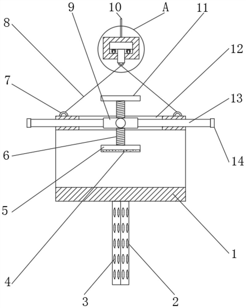
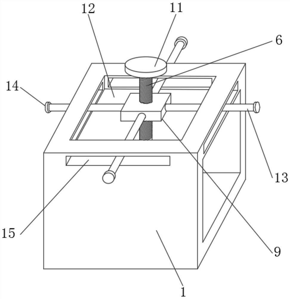
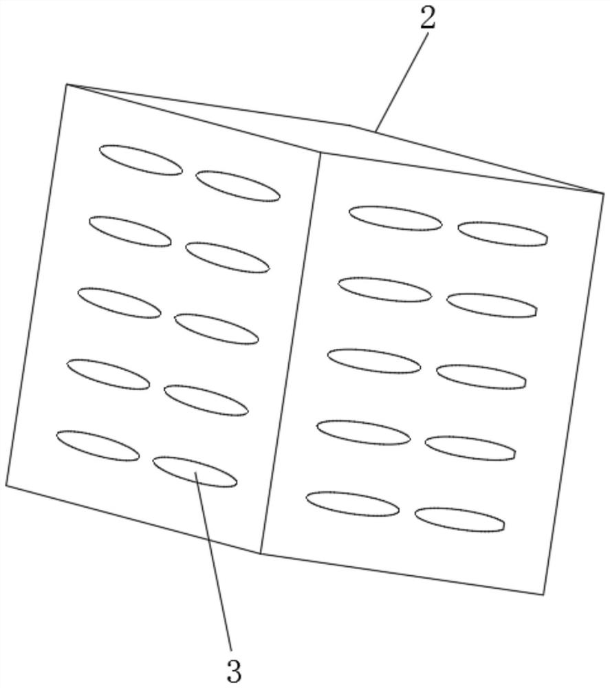
[0029] refer to Figure 1-4 , a construction material lifting device, comprising a lifting box 1 and a lifting part 16, the inner rotation of the lifting part 16 is provided with a turntable 17, the bottom outer wall of the turntable 17 is fixedly connected with a movable column 19, and the movable column 19 The outer wall of the bottom is fixedly connected with lifting rings 20, and the four corners of the top outer wall of the lifting box 1 are fixedly connected with fixing rings 7, and the fixing rings 7 and the lifting rings 20 are bolted by wire ropes 8, and the lifting box 1 is provided with a limit mechanism.

[0030] The outer wall of the bottom of the turntable 17 is fixedly connected with rollers 18 equidistant and circularly distributed, which can assist the rotation of the turntable 17 and make the rotation process of the turntable 17 smoother.

[0031] The limit mechanism comprises a movable plate 9, a stop plate 5 and a slide bar 13. The top outer wall of the li...

Embodiment 2

[0038] refer to Figure 5 , a lifting device for building materials in construction engineering. Compared with Embodiment 1, this embodiment also includes sleeves 21 fixedly connected to the four corners of the bottom outer wall of the lifting box 1, and the top inner wall of the sleeve 21 is fixedly connected to There is a spring 24, one end of the spring 24 is fixedly connected with a telescopic rod 22, and the bottom outer wall of the telescopic rod 22 is fixedly connected with a support plate 23.

[0039] Working principle: When in use, when the lifting box 1 falls to the ground, the support plate 23 first contacts the ground, and then the telescopic rod 22 is urged to compress the spring 24 in the sleeve 21, which can play a certain buffering role, so that the lifting box 1 1 It is more stable when landing, and the use effect is better.


PUM


Abstract

The invention discloses a constructional engineering building material hoisting device which comprises a hoisting box and a hoisting part. A rotary disc is rotatably arranged in the hoisting part, a movable column is fixedly connected to the outer wall of the bottom of the rotary disc, a hoisting ring is fixedly connected to the outer wall of the bottom of the movable column, fixing rings are fixedly connected to the four corners of the outer wall of the top of the hoisting box, and the fixing rings and the hoisting ring are in bolted connection through a steel wire rope; and the hoisting boxis provided with a limiting mechanism, the outer wall of the bottom of the rotary disc is fixedly connected with idler wheels which are annularly distributed at equal intervals, and the limiting mechanism comprises a movable plate, an abutting plate and a sliding rod. According to the constructional engineering building material hoisting device, building materials with different lengths and thicknesses can be fixedly hoisted, the use flexibility of the hoisting device is effectively improved, a guide plate at the bottom of the hoisting box can be kept in the position parallel to the wind direction, wind can penetrate through the hoisting box, the wind resistance of the guide plate can be effectively reduced through ventilation holes in the guide plate, and the stability in the hoisting process is effectively improved.

Description

technical field [0001] The invention relates to the technical field of building material lifting, in particular to a building material lifting device for construction engineering. Background technique [0002] When pouring reinforced concrete in a high-rise building, the frame and support method used requires a large number of iron parts to form a frame body. The formwork is laid on the frame body, and the frame body is stressed on the floor of the next floor. The structural frame The body needs to be hoisted to different floors with a hoisting device. [0003] At present, the existing building materials are usually hoisted by tower cranes. Most of them directly fix the steel on the cable and lift it directly. The steel is easy to slip off the cable. The lifting process is very dangerous and there is a great potential safety hazard. When using a special lifting device for lifting, it can only be used for specific steel materials. When encountering similar materials but inco...

Claims


Application Information

Patent Timeline
Patent Type & Authority Applications(China)
IPC IPC(8): B66C1/16F16F15/067
CPCB66C1/16F16F15/067
Inventor 杨庆美
Owner 杨庆美
Why Eureka
Try Eureka