Highway variable speed limit and lane change cooperative control method under vehicle-road cooperation

A technology of expressway, vehicle-road coordination, applied in the direction of controlling traffic signals, etc., can solve the problems of traffic flow, uncontrollable, vehicles unable to change lanes smoothly, etc., to reduce the capacity drop, improve traffic conditions, and improve traffic efficiency.

Active Publication Date: 2021-09-28
CHANGSHA UNIVERSITY OF SCIENCE AND TECHNOLOGY
View PDF19 Cites 13 Cited by
  • Summary
  • Abstract
  • Description
  • Claims
  • Application Information

AI Technical Summary

Problems solved by technology

The variable speed limit control dynamically adjusts the upstream traffic volume of the bottleneck area to maintain the traffic volume flowing into the bottleneck near its maximum capacity. speed control; when there are a large number of concentrated lane changes near the bottleneck, it will affect the traffic flow, cause congestion and queuing, and reduce the maximum traffic capacity of the bottleneck by 15%-25%, which will affect the implementation of the variable limit. speed control has a large negative impact, which is why variable speed limits sometimes fail to improve vehicle journey times
Lane change control enables vehicles to change lanes in advance when they are a certain distance away from the bottleneck by issuing lane change information, thereby reducing congestion near the bottleneck and eliminating queuing. Lane change
[0004] In the process of realizing the present invention, the inventor found that the existing variable speed limit control mainly has the following disadvantages: First, only a single variable speed limit control is used for the main line of the expressway, ignoring the impact of vehicle lane change on the variable speed limit Negative effects of control effects
Second, the existing variable speed limit control often implements the same speed limit value for all lanes in a certain speed limit section, without considering the difference between the maximum speed limit values ​​of different lanes on the expressway in practice, it is difficult to adapt to the vehicle The actual situation of split lane driving
Third, the existing variable speed limit is mainly when traffic congestion occurs in the bottleneck area, and the variable speed limit control is implemented on the upstream traffic flow, which cannot exert the active preventive effect of the variable speed limit, and it is difficult for the driver to detect Speed ​​limit information posted on variable information boards

Method used


Image

  • Highway variable speed limit and lane change cooperative control method under vehicle-road cooperation
  • Highway variable speed limit and lane change cooperative control method under vehicle-road cooperation
  • Highway variable speed limit and lane change cooperative control method under vehicle-road cooperation

Examples


Embodiment 1

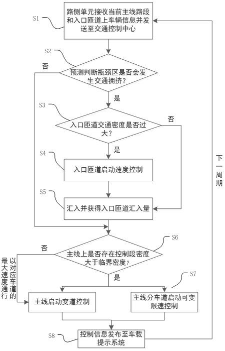
[0069] A coordinated control method for expressway variable speed limit and lane change under vehicle-road coordination, such as figure 1 As shown, follow the steps below:

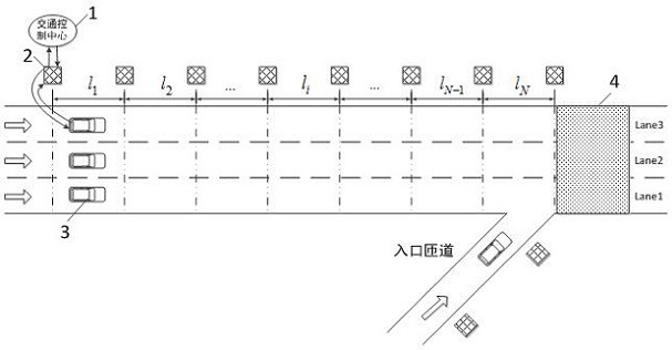
[0070] S1: Lay out roadside unit 2. Roadside unit 2 is arranged longitudinally along the roadside. The distance between two adjacent roadside units is 50m. Divide the highway section containing the entrance ramp into several control sections, and the main lane downstream of the entrance ramp is Bottleneck area 4; roadside unit 2 receives the information of all vehicles passing through all control sections of the current main line and on-ramps (that is, communication vehicles 3 ), and sends them to the traffic control center 1 .

[0071] S11: If figure 2 As shown, the control road section has two division dimensions, that is, the division along the direction of traffic flow and the division along the width direction of the highway; l The sections of the traffic flow are numbered sequentially from the up...

Embodiment 2

[0129] like figure 2 As shown, there is an expressway section with an entrance ramp, and its main line is two-way six-lane (one-way three-lane). The expressway section with an entrance ramp is divided into 10 identical sections with a length of 1 km, numbered 1 to 10, Right now N Equal to 10; each road segment is divided by lane, numbered 1 to 3 from the outer lane to the inner lane, that is J Equal to 3; one roadside unit is laid every 50m;

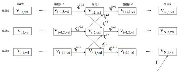
[0130] Assuming that the maximum capacity of each lane is 1800veh / h based on historical data, the maximum speed limits of lanes 1, 2, and 3 are 80, 100, and 120km / h respectively, and the critical densities are 23, 18, and 15veh / km / ln (vehicle / km / lane), namely =23 veh / km / ln, =18 veh / km / ln, =15veh / km / ln; Section 1 ( i =1) the critical density of the first lane and the road section N ( i = N ) is the same as the critical density of the first lane.

[0131] Critical density for on-ramps It is 18veh / km / ln, and the maximum sp...


PUM


Abstract

The invention discloses an highway variable speed limit and lane change cooperative control method under vehicle-road cooperation, and the method specifically comprises the steps: laying a road side unit, and dividing a highway section containing an entrance ramp into a plurality of control sections; predicting that traffic congestion will occur in the next period in the highway bottleneck area; controlling the speed of the vehicle on the entrance ramp in the current period; determining the critical density of the main line lane allowing convergence after convergence; judging whether the traffic density of each control road section on the highway main line in the next period is greater than the critical density of the main line lane allowing convergence after convergence or not; carrying out the variable speed limiting control and lane changing control on each control road section on the highway main line; issuing the control information to the vehicle-mounted prompting system, and regulating and controlling the flow flowing into the downstream. According to the invention, on the basis of real-time information sharing of vehicle-road cooperation, through cooperation of variable speed limit control and lane change control, the passing efficiency of the highway is improved, a large number of centralized lane change behaviors are reduced, and the risk of rear-end collision is reduced.

Description

technical field [0001] The invention belongs to the technical field of intelligent traffic management and control, and relates to a coordinated control method for variable speed limit and lane change of an expressway under vehicle-road coordination. Background technique [0002] The merge area of ​​expressway entrance ramp is one of the accident-prone road sections. When the traffic demand on the main line of the expressway and the entrance ramp is large, and the traffic volume upstream of the bottleneck is higher than the maximum capacity of the bottleneck, the bottleneck will be activated and congestion will occur; in addition, there may be a large number of concentrated lane-changing behaviors between the main line vehicles and the ramp-in vehicles near the bottleneck , resulting in vehicle speed shocks will increase the risk of rear-end collisions and further cause traffic flow disorder, resulting in reduced traffic capacity and aggravated the severity of traffic congest...

Claims


Application Information

Patent Timeline
Patent Type & Authority Applications(China)
IPC IPC(8): G08G1/08G08G1/07
CPCG08G1/08G08G1/07
Inventor 郝威邵敬波黄中祥戎栋磊吴其育王杰
Owner CHANGSHA UNIVERSITY OF SCIENCE AND TECHNOLOGY
Why Eureka
Try Eureka