Connector anti-loosening structure for underground high-temperature-resistant and high-voltage-resistant cable

A technology for high-voltage cables and cable joints, applied in the direction of cable joints, etc., can solve the problems of inability to disassemble, loosen, short-circuit, etc., and achieve the effect of improving practicability and improving the ability to prevent loosening.

Active Publication Date: 2021-09-28
辽宁沈鹏电力科技有限公司
View PDF12 Cites 1 Cited by
  • Summary
  • Abstract
  • Description
  • Claims
  • Application Information

AI Technical Summary

Problems solved by technology

[0004] 1. When the existing connectors are connected to the cables, the connectors will become loose after a long time of connection, resulting in unstable connection between the two cables and easy disconnection, which will cause two The temperature of the cable connection is too high, and a short circuit occurs;
[0005] 2. There is no ability to adjust the limit distance according to the locking distance of the joint, so when the locking distance of the joint changes, the locking structure of the joint cannot be effectively limited, which in turn affects the practical performance of the anti-loosening structure;
[0006] 3. Since there is no detachable function, when the anti-loosening structure is damaged, it cannot be effectively disassembled, resulting in the inability to perform anti-loosening work on the joints, which will affect the normal use of the joints
[0007] Therefore, the existing joint anti-loosening structure of underground high-temperature and high-voltage cables cannot meet the needs of actual use, so there is an urgent need for improved technology on the market to solve the above problems

Method used


Image

  • Connector anti-loosening structure for underground high-temperature-resistant and high-voltage-resistant cable
  • Connector anti-loosening structure for underground high-temperature-resistant and high-voltage-resistant cable
  • Connector anti-loosening structure for underground high-temperature-resistant and high-voltage-resistant cable

Examples


Embodiment Construction

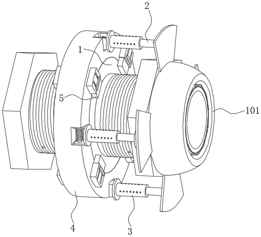
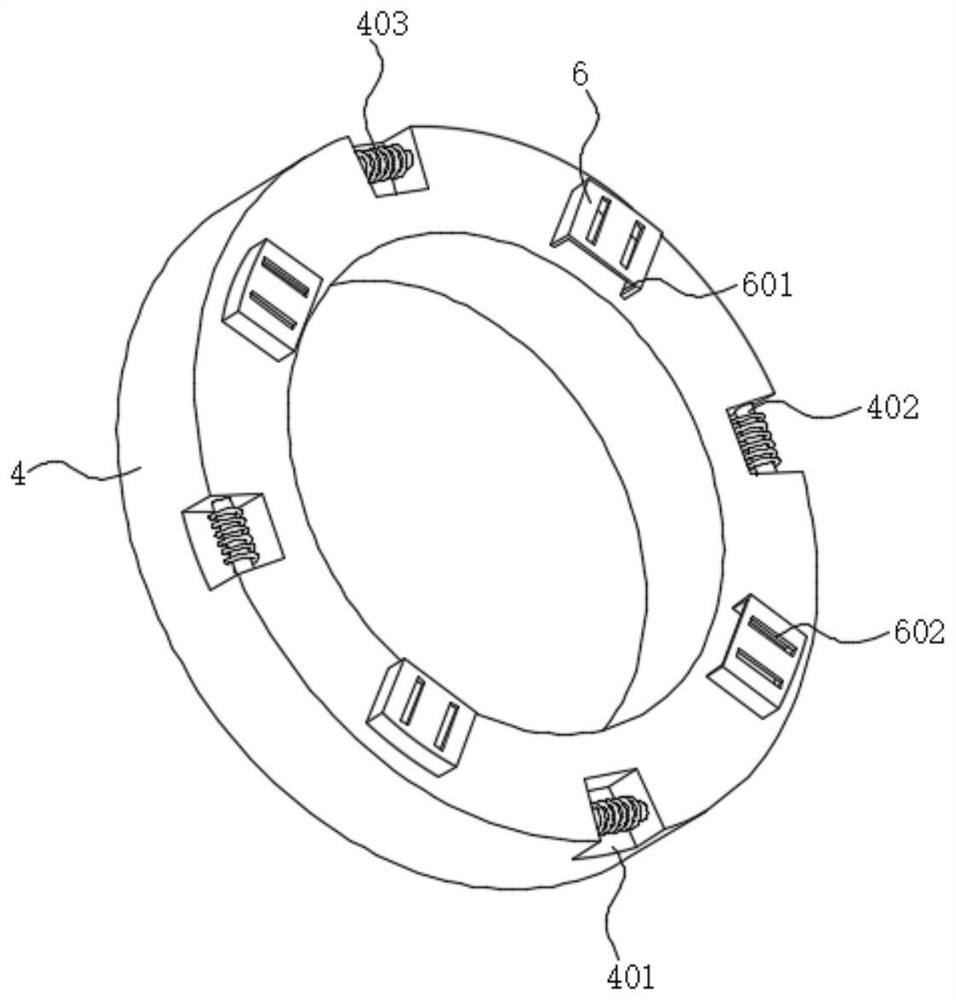
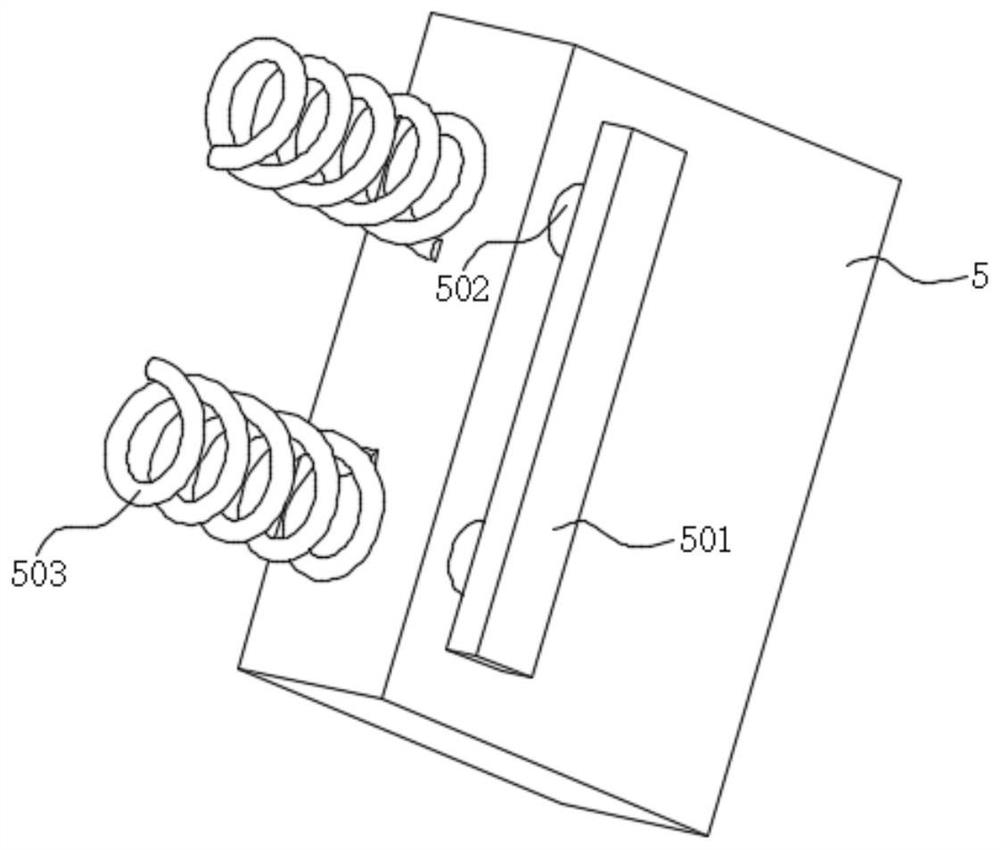
[0036] The following will clearly and completely describe the technical solutions in the embodiments of the present invention with reference to the drawings in the embodiments of the present invention.

[0037] see Figure 1-6 As shown, the present invention is a joint anti-loosening structure for underground high-temperature and high-voltage cables, including a cable joint body 1, and a mounting ring 4 is set on the surface side wall of the cable joint body 1, and the mounting ring 4 and a locking cap 101 Adjustment columns 3 are arranged between them, and the adjustment columns 3 are distributed in a circular array with four, the right side of the adjustment column 3 is provided with a limit hole 304, and the inner left side of the limit hole 304 is provided with a movable hole 305, and the movable hole The aperture of 305 is larger than the aperture of limit hole 304, and the right side of adjusting column 3 is provided with movable rod 2, and the right end of movable rod 2...


PUM


Abstract

The invention discloses a connector anti-loosening structure for an underground high-temperature-resistant and high-voltage-resistant cable, and relates to the technical field of cable laying and mounting equipment. The connector anti-loosening structure comprises a cable connector body, wherein the surface side wall of the cable connector body is sleeved with a mounting ring, storage plates are fixed to the left side wall and the right side wall of the mounting ring, storage openings are formed in the side walls, which are close to the mounting ring, of the storage plates, baffles are arranged in the storage openings, an adjusting column is arranged between the mounting ring and a locking cap, a movable hole is formed in the left side of the interior of the limiting hole, a movable rod is arranged on the right side of the adjusting column, clamping plates are fixed to the right ends of the movable rods, and movable plates are fixed to the left ends of the movable rods. According to the invention, the locking cap is abutted and blocked by the four clamping plates, the anti-loosening stability is improved, the movable plate moves in the movable hole, so that the distance of the clamping plates is adjusted, the adjustment work is carried out according to the position of the locking cap, the top plate is moved into the storage opening of the storage plate, and the mounting ring is conveniently detached and taken out from the cable connector body.

Description

technical field [0001] The invention belongs to the technical field of cable laying and installation equipment, in particular to a joint anti-loosening structure used for underground high-temperature and high-voltage cables. Background technique [0002] Cables are often laid in cable trenches, tunnels, pipes or indoors. After entering the modern society, due to the shortage of urban land, high traffic pressure, city appearance construction and other reasons, large cities generally use underground cable transmission methods. Compared with overhead lines, cables have a large area. Small size, reliable power transmission, strong anti-interference ability, etc., when laying underground cables, cable joints are often used; [0003] The cable joint is also called the cable head. After the cable is laid, in order to make it a continuous line, each section of the line must be connected as a whole. The cable joint in the middle of the cable line is called the middle joint, and the c...

Claims


Application Information

Patent Timeline
IPC IPC(8): H02G15/08
CPCH02G15/08
Inventor 胡红媛
Owner 辽宁沈鹏电力科技有限公司
Why Eureka
Try Eureka