Shockproof base for civil engineering
A technology of civil engineering and fixed plates, which is applied to the frame of the engine, the mobile frame, the supporting machine, etc., can solve the problems of easy wear and tear of the shock absorbing pad and reduce the shockproof performance, so as to prolong the service life, reduce the risk of tire blowout, and improve The effect of mobility
- Summary
- Abstract
- Description
- Claims
- Application Information
AI Technical Summary
Problems solved by technology
Method used
Image

Examples
Embodiment Construction
[0035] The following is attached Figure 1-5 The application is described in further detail.
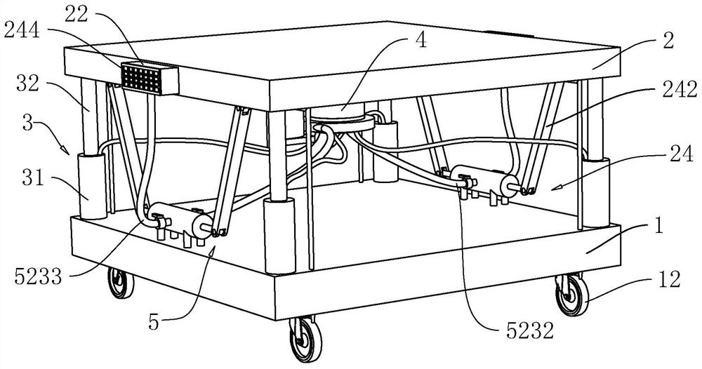
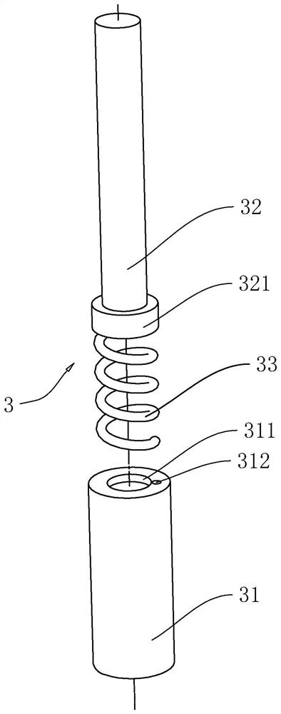
[0036] The embodiment of the present application discloses an anti-vibration base for civil engineering. refer to figure 1 , a kind of anti-vibration base for civil engineering includes a first fixed plate 1, and the bottom of the first fixed plate 1 rotates with rotating wheels 12. In the embodiment of the present application, the number of rotating wheels 12 is 4, which are respectively located at the four corners of the first fixed plate 1 , it is convenient to carry and move the base, saving manpower. A second fixed plate 2 slides on the first fixed plate 1, and the second fixed plate 2 is located above the first fixed plate 1. The side of the second fixed plate 2 away from the first fixed plate 1 is fixed with large equipment by bolts. A fixed plate 1 is connected to a second fixed plate 2 through an elastic member 3 . The side of the second fixed plate 2 facing the first fi...
PUM
 Abstract
Description
Claims
Application Information
 - R&D
- Intellectual Property
- Life Sciences
- Materials
- Tech Scout
- Unparalleled Data Quality
- Higher Quality Content
- 60% Fewer Hallucinations
Browse by: Latest US Patents, China's latest patents, Technical Efficacy Thesaurus, Application Domain, Technology Topic, Popular Technical Reports.
© 2025 PatSnap. All rights reserved.Legal|Privacy policy|Modern Slavery Act Transparency Statement|Sitemap|About US| Contact US: help@patsnap.com