Novel aluminum-plated high-strength reflective film preparation device
A technology for preparing a device and a reflective film, which is used in mixers with rotary stirring devices, mixer accessories, mixers, etc.
- Summary
- Abstract
- Description
- Claims
- Application Information
AI Technical Summary
Problems solved by technology
Method used
Image
Examples
Embodiment 1
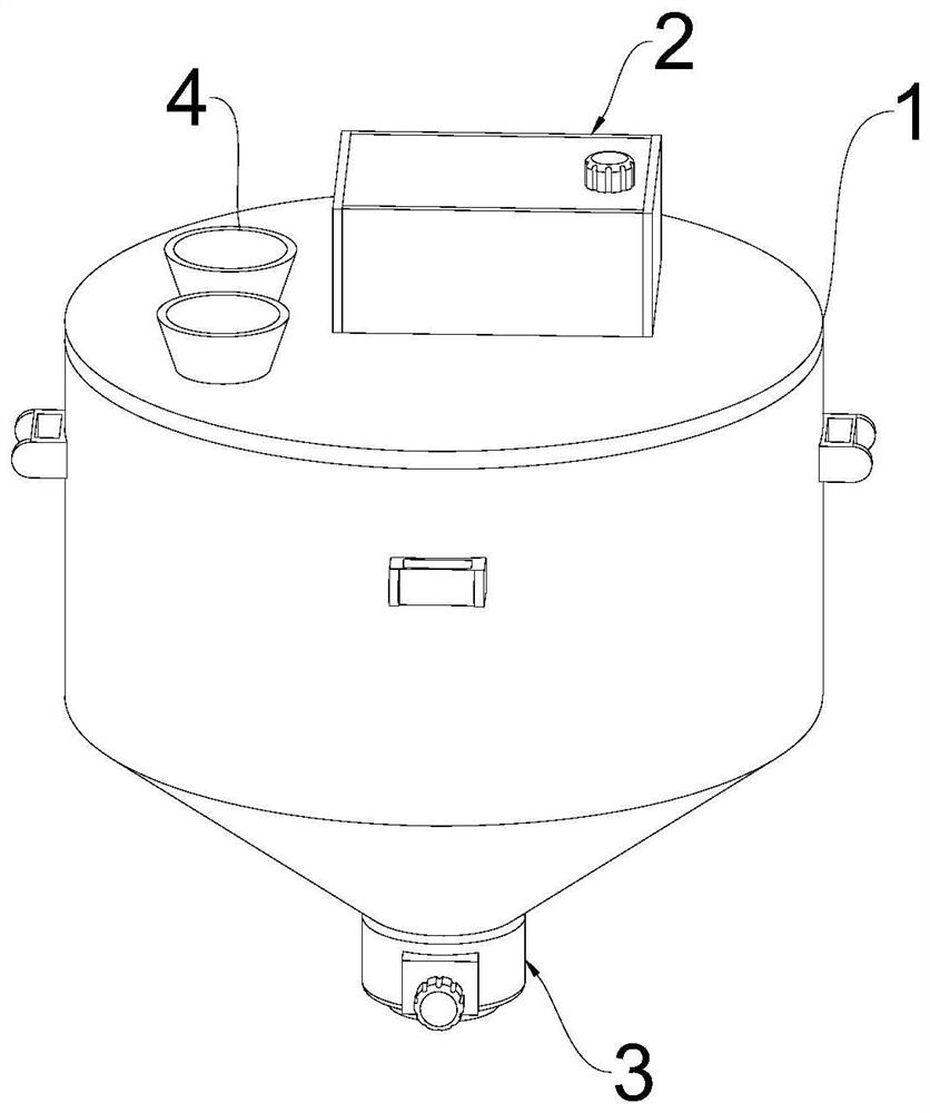
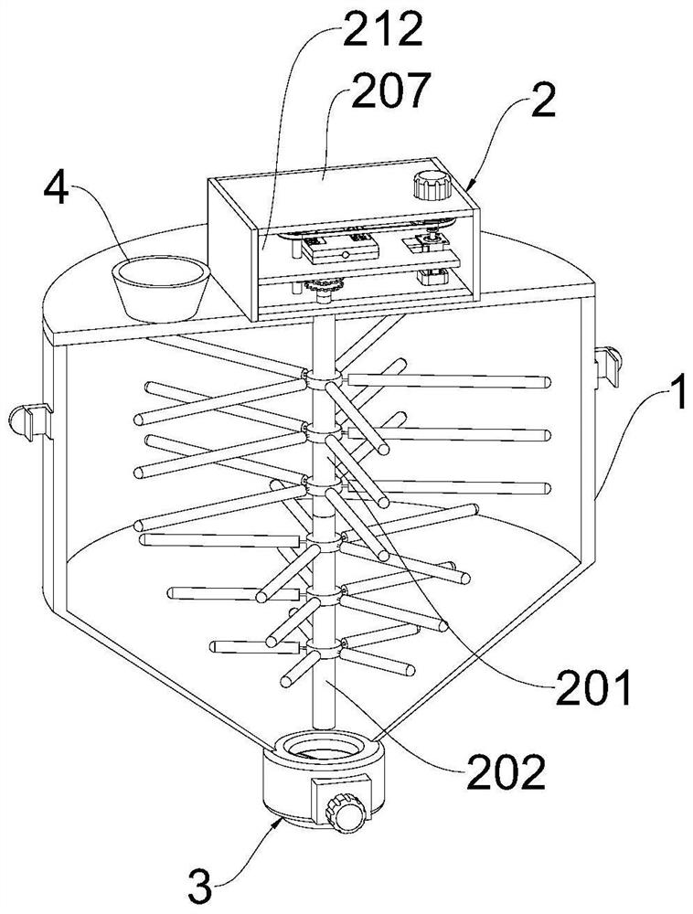
[0030] see Figure 1-2 , a new type of aluminum-plated high-strength reflective film preparation device, including a stirring tank 1, a stirring mechanism 2, and a discharge adjustment component 3. , the outside of the stirring tank 1 is fixed with a plurality of fixing bolts, the stirring mechanism 2 is arranged on the top of the stirring tank 1, and the stirring tank 1 is provided with a feeding trough 4 at both sides of the stirring mechanism 2.
[0031] The invention provides a new type of aluminum-plated high-strength reflective film preparation device. A stirring mechanism 2 extending to the inside of the stirring tank 1 is provided on the top surface of the stirring tank 1. The stirring mechanism 2 includes an upper stirring rod 201 and a lower stirring rod 202 for stirring up and down. , to achieve convective stirring and increase the stirring of the pot. The stirring mechanism 2 also includes a stirring rate adjustment structure, which increases the stirring efficienc...
Embodiment 2
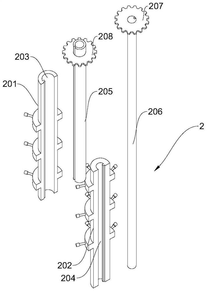
[0033] see Figure 2-3 , based on Embodiment 1, the difference is that the stirring mechanism 2 includes an upper stirring rod 201 and a lower stirring rod 202, and the upper stirring rod 201 is vertically arranged at the inside of the stirring tank 1 and its top is connected with the top of the mixing tank 1 for rotation, The bottom of the upper stirring rod 201 is rotationally connected with the top of the lower stirring rod 202. A chute A203 runs through the middle of the upper stirring rod 201, and a chute B204 runs through the middle of the lower stirring rod 202. A rotating shaft A205 is provided for sliding inside the chute A203. A rotating shaft B206 is slidably provided inside the chute B204.
[0034] In the present invention, the upper stirring rod 201 and the lower stirring rod 202 are vertically arranged inside the stirring tank 1 and are connected to each other in rotation, respectively set up a chute A203 and a chute B204 on the upper stirring rod 201 and the low...
Embodiment 3
[0036] see Figure 2-5, based on Embodiment 1-2, the difference lies in that the stirring mechanism 2 includes a driving box 207, the rotating shaft A205 extends upwards to the inside of the driving box 207 and is connected to it in rotation, the outer wall of the top end of the rotating shaft A205 is sleeved with a gear A208, and the rotating shaft B206 is upward Extending through the middle part of the rotating shaft A205 to the top and rotatingly connected with it, the top of the rotating shaft B206 is sleeved with a gear B209, the outer side of the gear A208 is meshed with the gear C210, the outer side of the gear B209 is meshed with the gear D211, and the gear C210 is meshed with the gear B209.
[0037] The limiting plate 212 is fixed in the middle part of the drive box 207, the middle rotating rod of the gear D211 extends upwards to the top of the limiting plate 212 and is fixedly connected with the rotating wheel A213, the outer side of the rotating wheel A213 is covered...
PUM
 Abstract
Description
Claims
Application Information
 - R&D
- Intellectual Property
- Life Sciences
- Materials
- Tech Scout
- Unparalleled Data Quality
- Higher Quality Content
- 60% Fewer Hallucinations
Browse by: Latest US Patents, China's latest patents, Technical Efficacy Thesaurus, Application Domain, Technology Topic, Popular Technical Reports.
© 2025 PatSnap. All rights reserved.Legal|Privacy policy|Modern Slavery Act Transparency Statement|Sitemap|About US| Contact US: help@patsnap.com


