A draft self-twisting device and its ring spinning frame
A technology of twisting device and drafting device, which is applied in the direction of spinning machine, continuous winding spinning machine, textile and paper making, etc. It can solve the problem of insufficient yarn cohesion, uneven twisting and unsatisfactory twisting effect and other issues to achieve the effect of improving the winding effect
- Summary
- Abstract
- Description
- Claims
- Application Information
AI Technical Summary
Problems solved by technology
Method used
Image
Examples
Embodiment 1
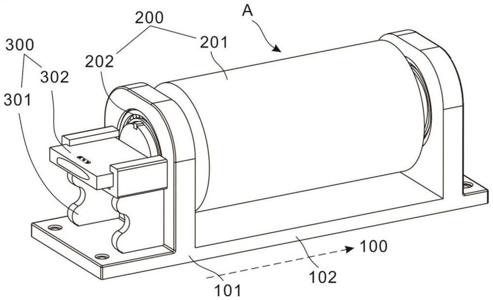
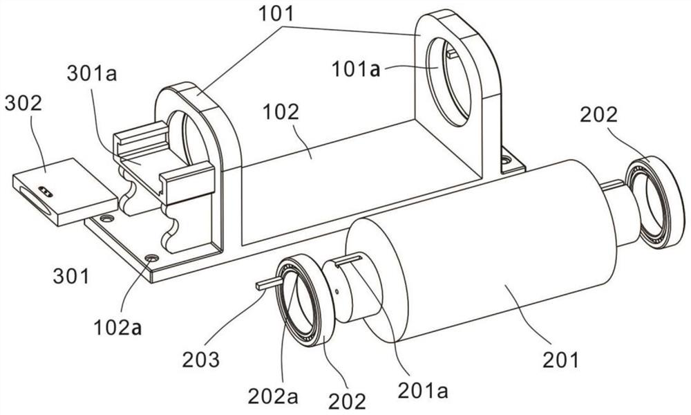
[0034] refer to Figures 1 to 4 , which is the first embodiment of the present invention, provides a drafting self-twisting device. The drafting self-twisting device A includes a support unit 100 and a self-twisting unit 200 .
[0035] The support unit 100 is an installation bracket of the self-twisting unit 200, and can be used for the external installation of the drafting self-twisting device A. Specifically, support plates 101 are symmetrically arranged on both sides of the support plate 101. Mounting groove 101a. The support plate 101 is a plate body arranged in parallel, the self-twisting unit 200 is installed between the two parallel support plates 101 , the installation groove 101 a is opened at the free end of the support plate 101 , and the installation groove 101 a penetrates the plate body of the support plate 101 .
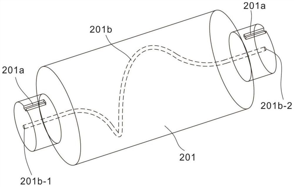
[0036] The self-twisting unit 200 is used for twisting after the yarn is drawn. Specifically, the self-twisting unit 200 is arranged between the two ...
Embodiment 2
[0045] refer to figure 1 , 5 and 6, for the second embodiment of the present invention, a drafting self-twisting device is provided. In addition to the drafting self-twisting device A including the supporting unit 100 and the self-twisting unit 200 in the above-mentioned embodiment 1, An aggregation unit 300 is also included.
[0046] The collecting unit 300 is used for combing and collecting after the yarn is drawn and before twisting; specifically, it is arranged on the side wall of the support plate 101, and includes a support table 301 and a collector 302 arranged on the support table 301, The output end of the collector 302 is matched with the input end of the self-twisting drum 201 . The support table 301 is connected to the end side wall of a support plate 101 for supporting and installing the collector 302, and the collector 302 is used for combing and collecting the drawn yarns so that they can enter in a predetermined twisting direction in the self-twisting drum 2...
Embodiment 3
[0052] refer to Figure 7 , is the third embodiment of the present invention, this embodiment provides a ring spinning frame, the ring spinning frame is installed with the drafting self-twisting device A in the above-mentioned embodiment 2, and is arranged in the drafting self-twisting device A between the stretching device 400 and the yarn guide 500.
[0053] Further, the roving S is wound on the roving roller, drawn out through the yarn guide rod, introduced into the drafting device 400 from the bell mouth, drawn out after drafting, and passed out from the drafting self-twisting device A to form the spun yarn X, The spun yarn X is finally wound on the take-up roll via the yarn guide.
[0054] The drafting self-twisting device A is set between the drafting device 400 and the yarn guide 500, its input end receives the yarn drawn and output from the drafting device 400, and its output end will complete the self-twisting yarn Yarn output.
[0055] Specifically, the roving S i...
PUM
 Abstract
Description
Claims
Application Information
 - R&D
- Intellectual Property
- Life Sciences
- Materials
- Tech Scout
- Unparalleled Data Quality
- Higher Quality Content
- 60% Fewer Hallucinations
Browse by: Latest US Patents, China's latest patents, Technical Efficacy Thesaurus, Application Domain, Technology Topic, Popular Technical Reports.
© 2025 PatSnap. All rights reserved.Legal|Privacy policy|Modern Slavery Act Transparency Statement|Sitemap|About US| Contact US: help@patsnap.com


