Prefabricated bridge deck formwork-free cast-in-place wet joint structure

A prefabricated panel and wet joint technology, applied in bridges, bridge parts, bridge construction and other directions, can solve the problems of poor quality controllability, large formwork workload, hidden safety hazards under bridges, etc., to ensure installation accuracy and reduce Construction costs and the effect of avoiding potential safety hazards

Pending Publication Date: 2021-10-08
中铁长江交通设计集团有限公司
View PDF0 Cites 0 Cited by
  • Summary
  • Abstract
  • Description
  • Claims
  • Application Information

AI Technical Summary

Problems solved by technology

Among them, the wet joint is the key point in the design of the steel-concrete composite beam to ensure that the prefabricated components are assembled to form a stable whole. At present, when the conventional steel-concrete composite beam is used for the longitudinal wet joint of the bridge deck, it is completed after the erection of the prefabricated bridge deck Finally, it is first necessary to set up formwork at the reserved wet joint position, and then pour concrete in the wet joint section. This method has the following disadvantages: 1. The workload of setting up the formwork on site is relatively large, and the quality controllability is poor, which affects the structural strength of the wet joint; 2. , Increase the construction cost and the risk of high-altitude operations; 3. Before the formwork is completed, it will inevitably cause safety hazards to pass under the bridge

Method used


Image

  • Prefabricated bridge deck formwork-free cast-in-place wet joint structure
  • Prefabricated bridge deck formwork-free cast-in-place wet joint structure
  • Prefabricated bridge deck formwork-free cast-in-place wet joint structure

Examples


Embodiment

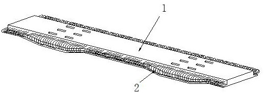
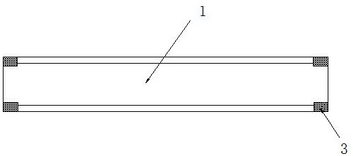
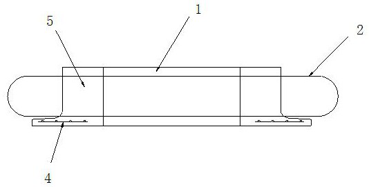
[0022] see Figure 1-Figure 5 , the specific embodiments of the present invention are as follows: a prefabricated bridge deck cast-in-place wet joint structure without formwork, its structure includes a plurality of prefabricated slabs 1 arranged along the bridge direction, and two adjacent prefabricated slabs 1 are continuously laid The cast-in-place section 8 between the slabs 1, the prefabricated slab 1 is provided with a half "U"-shaped structure extension 5 along the bridge to both ends, and the half "U"-shaped structure of two adjacent prefabricated slabs The extension section is butted to form a whole "U" shape. The notch 6 is used as the bottom form of the cast-in-place section 8, which saves a large amount of formwork engineering work on site, and effectively controls the construction process quality of the wet joint structure to ensure the structure Stress continuity at wet joints; the cast-in-place section 8 is poured and connected with two adjacent prefabricated sl...


PUM


Abstract

The invention discloses a prefabricated bridge deck formwork-free cast-in-place wet joint structure, and belongs to the technical field of bridge design, the prefabricated bridge deck formwork-free cast-in-place wet joint structure comprises a plurality of prefabricated slabs arranged in the bridge direction and cast-in-place sections continuously laid between every two adjacent prefabricated slabs, and the two ends of each prefabricated slab in the bridge direction are provided with semi-U-shaped structure extension sections; the semi-U-shaped structure extension sections of every two adjacent prefabricated slabs are in butt joint to form a whole U-shaped notch to serve as a bottom die of the cast-in-place section, the cast-in-place section is connected with the two adjacent prefabricated slabs in a pouring mode, and the prefabricated slabs and the cast-in-place section are made of concrete materials or ultra-high-performance concrete materials. On-site template loading and unloading work is omitted, construction is facilitated and the manufacturing cost is reduced, potential safety hazards of passing under the bridge in the construction process are avoided, and the quality of the wet joint structure is improved to the maximum extent.

Description

technical field [0001] The invention relates to the field of bridge design, in particular to a prefabricated bridge deck cast-in-place wet joint structure without templates. Background technique [0002] The steel-concrete composite girder bridge is a structural form different from traditional girder bridges developed on the basis of steel girders and reinforced concrete girders by combining the respective advantages of the two materials. It can realize standardized design, industrialized manufacturing, and assembly to the greatest extent. In recent years, it has been widely used in the field of bridge engineering because of its simplified construction and reduced on-site operations. Among them, the wet joint is the key point in the design of the steel-concrete composite beam to ensure that the prefabricated components are assembled to form a stable whole. At present, when the conventional steel-concrete composite beam is used for the longitudinal wet joint of the bridge dec...

Claims


Application Information

Patent Timeline
Patent Type & Authority Applications(China)
IPC IPC(8): E01D19/06
CPCE01D19/067
Inventor 陈奉民刘小辉谢小华郑升宝吴勇张昊
Owner 中铁长江交通设计集团有限公司
Why Eureka
Try Eureka