
Floating ash treatment mechanism in drainage pipeline

A technology for drainage pipes and floating ash, which is applied to the field of floating ash treatment mechanisms in drainage pipes, can solve the problems of troublesome cleaning process, time-consuming and laborious, poor practicability, etc., and achieves the effects of good cleaning effect, convenient use and effective treatment.

Active Publication Date: 2022-03-11
HUANENG CHAOHU POWER GENERATION
View PDF0 Cites 0 Cited by
  • Summary
  • Abstract
  • Description
  • Claims
  • Application Information

AI Technical Summary

Problems solved by technology

[0004] The purpose of the present invention is to solve the problem that the cleaning process in the prior art is too cumbersome, time-consuming and laborious, and the cleaning efficiency is not high; at the same time, the device cannot be cleaned by itself, and the practicability is poor; it is also impossible to effectively clean the "stubborn" dust. The effect is not good, and a floating ash treatment mechanism in the drainage pipeline is proposed

Method used


Image

  • Floating ash treatment mechanism in drainage pipeline
  • Floating ash treatment mechanism in drainage pipeline
  • Floating ash treatment mechanism in drainage pipeline

Examples


Embodiment Construction

[0030] The following will clearly and completely describe the technical solutions in the embodiments of the present invention with reference to the accompanying drawings in the embodiments of the present invention. Obviously, the described embodiments are only some, not all, embodiments of the present invention.

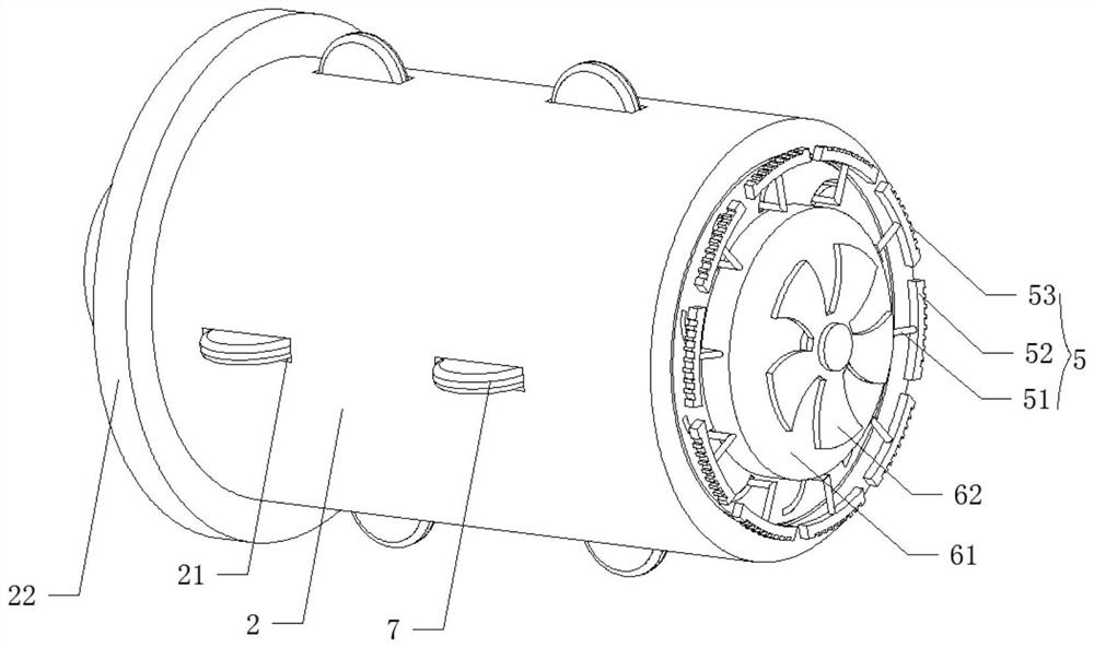
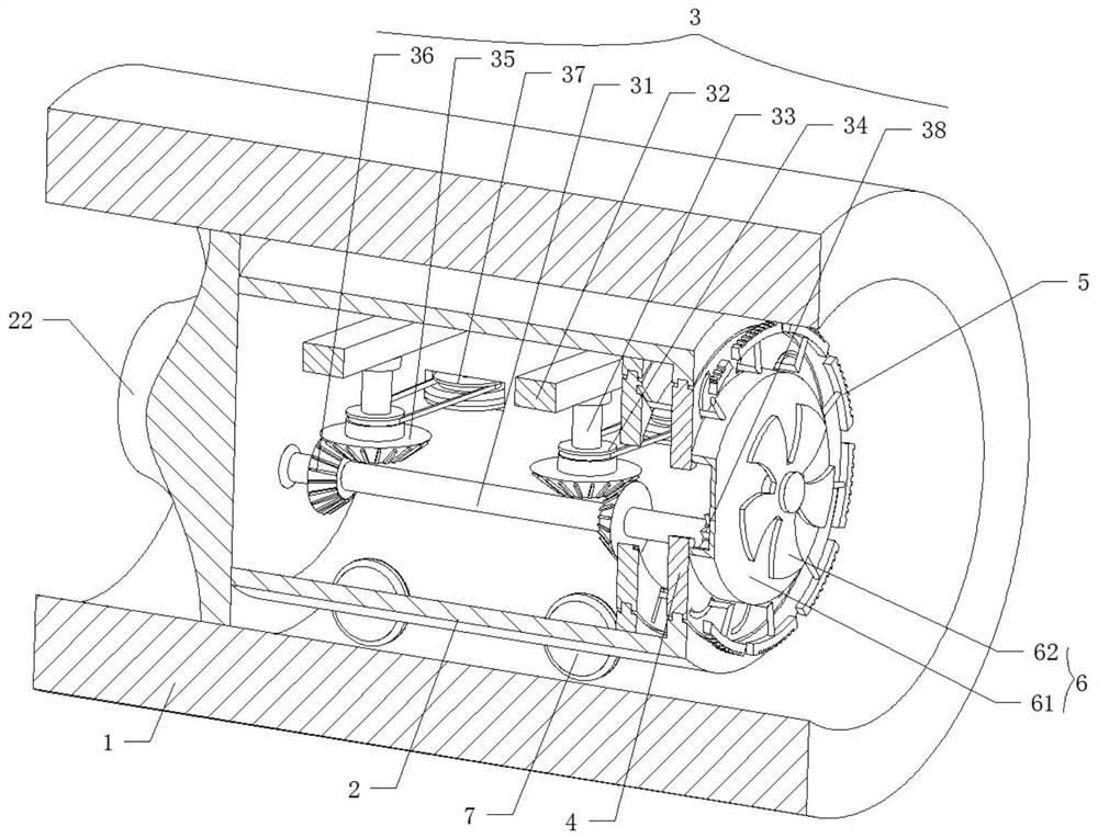
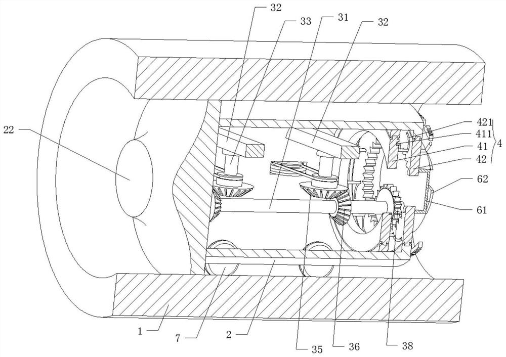
[0031] refer to figure 1 , figure 2 , image 3 , a floating ash treatment mechanism in a drainage pipeline, comprising:

[0032] The pipe 1 and the shell 2, the shell 2 is slidably arranged in the inner cavity of the pipe 1, the shell 2 is used to clean the inner wall of the pipe 1, and the side wall of the shell 2 is provided with an annular groove 21;

[0033] The drive assembly 3, the drive assembly 3 is fixedly installed inside the housing 2;

[0034] Rotating assembly 4, rotating assembly 4 is rotatably connected to the right part of housing 2, rotating assembly 4 is engaged with driving assembly 3, and driving assembly 3 is used to drive rotating assembly 4...


PUM


Abstract

The invention discloses a floating ash treatment mechanism in a drainage pipeline, which relates to the field of drainage pipeline cleaning, comprising: a pipeline and a casing, the casing is slidably arranged in the inner cavity of the pipeline; a driving assembly, and the driving assembly is fixedly installed on the casing Inside: the rotating assembly, the rotating assembly is rotatably connected to the right part of the housing, and the driving assembly is used to drive the rotating assembly to rotate; the cleaning assembly, the cleaning assembly is slidably connected to the side wall of the rotating assembly; the blowing assembly , the blowing assembly is fixedly installed with the end of the rotating assembly; the blowing assembly is used to blow out the floating ash. The present invention converts the driving force of the water flow into the driving force required for rotating and cleaning through the setting of the driving component, which is simple, fast and convenient to use without manual operation. Carry out rotary push cleaning, thereby improving the cleaning effect of the device.

Description

technical field [0001] The invention relates to the technical field of drain pipe cleaning, in particular to a floating ash treatment mechanism in the drain pipe. Background technique [0002] Drainage pipeline refers to the system composed of pipes and channels and their ancillary facilities for collecting and discharging sewage, waste water and rainwater. Including main pipes, branch pipes and pipelines leading to treatment plants, no matter they are built on the street or anywhere else, as long as they are used for drainage, they should be counted as drainage pipelines, but the most obvious problems in the use of drainage pipelines That is, the inner wall of the pipeline is difficult to clean, and the fluid formed by floating ash is prone to sediment during pipeline transportation. When the pump or other power source provides power, the power will be weakened by the friction of the pipeline on the fluid, to a large extent. Reduce the transportation efficiency of drainage...

Claims


Application Information

Patent Timeline
Patent Type & Authority Patents(China)
IPC IPC(8): E03F7/10E03F9/00
CPCE03F7/10E03F9/002
Inventor 乔鑫肖波陆爱行王亮
Owner HUANENG CHAOHU POWER GENERATION
Learn More