
Cutting head for heading machine and heading machine

A technology of roadheader and cutting head, which is applied in the direction of mechanical equipment, mining equipment, tunnels, etc. It can solve the problem of inconvenient disassembly of the cutting head, shock absorption of the cutting head, etc., and achieve the effect of improving the replacement efficiency and reducing the probability of damage

Inactive Publication Date: 2021-10-08
杭州正昇安全科技有限公司
View PDF0 Cites 1 Cited by
  • Summary
  • Abstract
  • Description
  • Claims
  • Application Information

AI Technical Summary

Problems solved by technology

[0004] The purpose of the present invention is to provide a cutting head for a roadheader and a roadheader to solve the problems in the prior art that it is inconvenient to disassemble the cutting head and lack shock absorption for the cutting head in the above-mentioned background technology

Method used

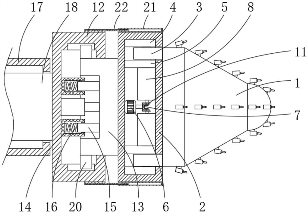
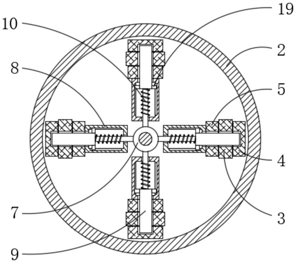
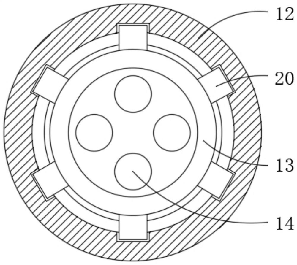

Image

  • Cutting head for heading machine and heading machine
  • Cutting head for heading machine and heading machine
  • Cutting head for heading machine and heading machine

Examples


Embodiment Construction

[0023] The following will clearly and completely describe the technical solutions in the embodiments of the present invention with reference to the accompanying drawings in the embodiments of the present invention. Obviously, the described embodiments are only some, not all, embodiments of the present invention. The specific embodiments described here are only used to explain the present invention, not to limit the present invention. Based on the embodiments of the present invention, all other embodiments obtained by persons of ordinary skill in the art without making creative efforts belong to the protection scope of the present invention.

[0024] The present invention provides such Figure 1-4 The cutting head for the roadheader and the roadheader shown include a cutting head body 1, a plurality of cutting blades are fixedly installed on the surface of the cutting head body 1, and a limiting pipe 2 is arranged on one side of the cutting head body 1, The upper and lower end...


PUM


Abstract

The invention discloses a cutting head for a heading machine and the heading machine. The cutting head comprises a cutting head body, wherein a plurality of cutting blades are fixedly mounted on the surface of the cutting head body; a limiting pipe is arranged on one side of the cutting head body; limiting plates are fixedly mounted at the upper and lower ends and the front and rear ends of one side of the cutting head body; one side of each limiting plate penetrates through the limiting pipe and extends to an inner cavity of the limiting pipe; a supporting plate is fixedly mounted in the inner cavity of the limiting pipe and is positioned on the outer side of the limiting plate; a supporting plate is fixedly mounted in the inner cavity of the limiting pipe and is positioned on the inner side of the limiting plate; when the cutting blades are greatly abraded and need to be replaced, a motor is started, an output shaft of the motor drives a first gear to rotate, the first gear drives a second gear to rotate, the second gear drives a threaded rod to rotate, and the threaded rod drives a moving rod to move; and when the moving rod is separated from a clamping state with the limiting plate, the motor is stopped, the cutting head is taken out and replaced with a new cutting head, and the replacement efficiency is improved.

Description

technical field [0001] The invention belongs to the technical field of roadheaders, and in particular relates to a cutting head for a roadheader and a roadheader. Background technique [0002] The roadheader is a machine used to excavate roadways on flat ground. There are many types of roadheaders: ordinary machines and tunnel boring machines according to the operating objects; open type roadheaders and shield type roadheaders according to the operation method. The working method: It is mainly composed of a traveling mechanism, a working mechanism, a loading mechanism and a reloading mechanism. As the traveling mechanism advances, the cutting head in the working mechanism continuously breaks rocks and transports the broken rock away, which has the advantages of safety, high efficiency and good roadway quality. Advantages, but the cost is high, the structure is complicated, and the loss is also large. [0003] However, in existing coal mine roadheaders, the cutting head is n...

Claims


Application Information

Patent Timeline
IPC IPC(8): E21D9/10F16F15/067
CPCE21D9/1006F16F15/067
Inventor 孙嘉聆
Owner 杭州正昇安全科技有限公司
Learn More