
Industrial Internet of Things control box

An industrial Internet of Things, control box technology, applied in the cleaning method using tools, cabinet/box/drawer parts, electrical equipment housing/cabinet/drawer, etc. The problems such as the shielding of the heat dissipation port can reduce the internal moisture weight, improve the service life and reduce the probability of damage.

Pending Publication Date: 2021-10-08
南京盈呗信息科技股份有限公司
View PDF13 Cites 1 Cited by
  • Summary
  • Abstract
  • Description
  • Claims
  • Application Information

AI Technical Summary

Problems solved by technology

[0004]The industrial Internet of Things data acquisition control box increases the overall weight of the storage box by collecting rainwater, and cooperates with the baffle to press down to cover the cooling holes, preventing the cooling holes from being blocked. The effect of rainwater entering and causing damage to components, and the natural drying of the rainwater in the storage box with the baffle to lift and reset, thereby opening the cooling holes and continuing the heat dissipation work, but this technical solution does not consider the actual use process, whether it is rainwater It takes a certain amount of time to collect or dry the rainwater naturally. During this process, the displacement reaction time of the baffle is relatively long, so that it can not effectively protect the rain, and at the same time, it may cause the cooling outlet to be covered, and the heat dissipation will not be timely. The electrical components inside the box are damaged due to excessive temperature

Method used


Image

  • Industrial Internet of Things control box
  • Industrial Internet of Things control box
  • Industrial Internet of Things control box

Examples


Embodiment Construction

[0035] The following will clearly and completely describe the technical solutions in the embodiments of the present invention with reference to the accompanying drawings in the embodiments of the present invention. Obviously, the described embodiments are only some, not all, embodiments of the present invention. Based on the embodiments of the present invention, all other embodiments obtained by persons of ordinary skill in the art without making creative efforts belong to the protection scope of the present invention.

[0036] see Figure 1 to Figure 8 , the present invention provides a technical solution:

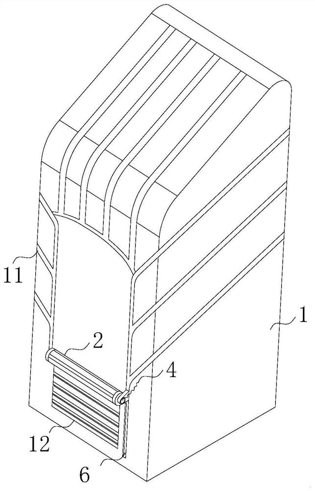
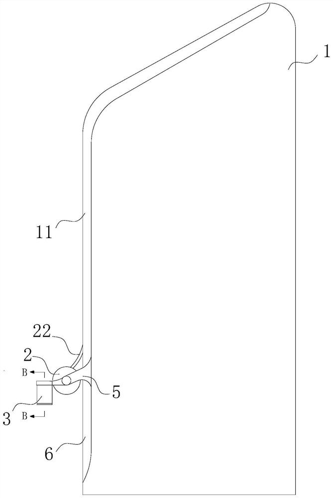
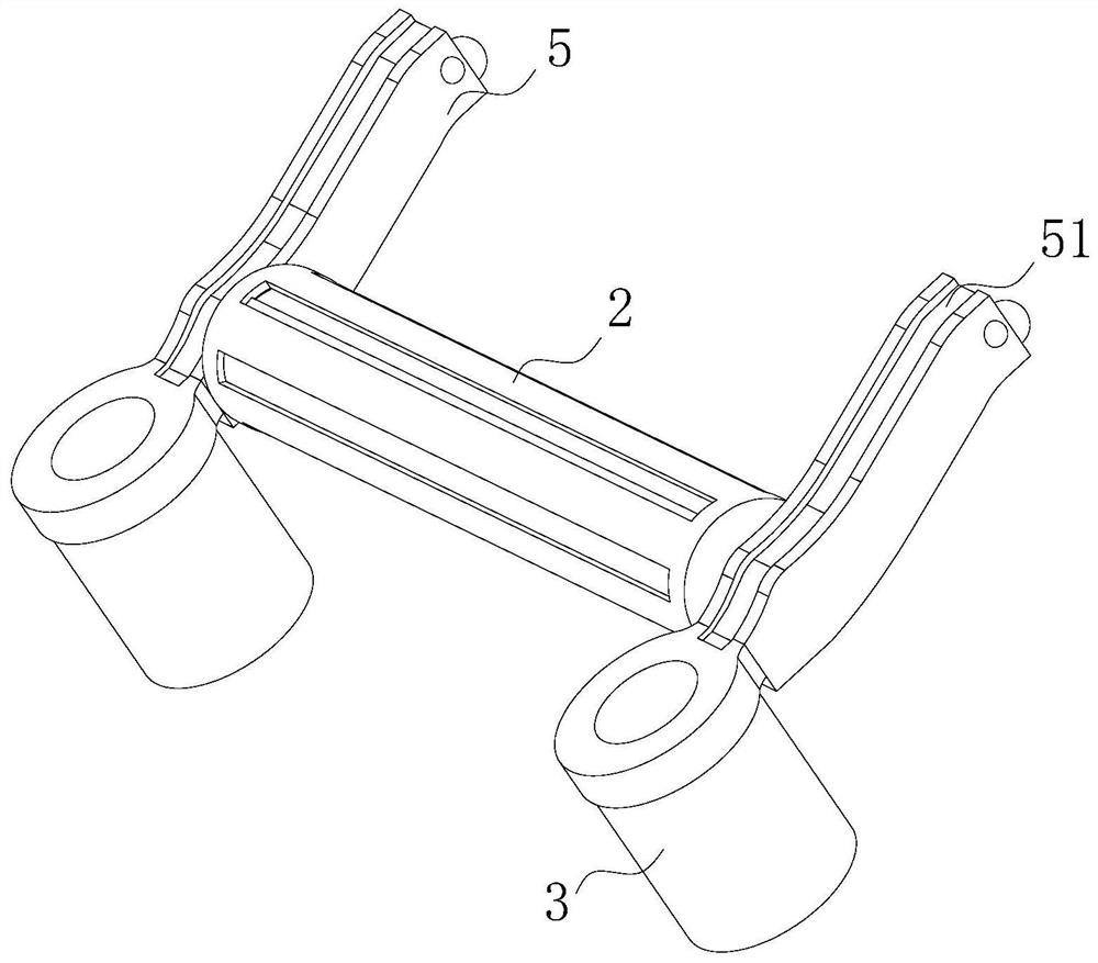
[0037]An industrial Internet of Things control box, comprising a box body 1 and several groups of drainage channels 11 arranged obliquely on the outer surface of the box body 1, several groups of the drainage channels 11 are connected, and the lower end of the front surface of the box body 1 is provided with a heat dissipation window 12, and both sides of the heat dissip...


PUM


Abstract

The invention relates to the technical field of Internet of Things control boxes, in particular to an industrial Internet of Things control box which comprises a box body and a plurality of drainage channels obliquely arranged on the outer surface of the box body, wherein the drainage channels are communicated, a heat dissipation window is arranged at the lower end of the front end face of the box body, sliding grooves are symmetrically formed in the two sides of the heat dissipation window, a shielding mechanism is arranged on the upper side of the heat dissipation window, sliding supports are fixedly connected to the two sides of the shielding mechanism correspondingly, and extension springs are hooked to the opposite faces of the two sliding supports correspondingly. By arranging a driving mechanism and a shielding mechanism, during rainfall, through the drainage channels arranged on the surface of the box body, rainwater dripping from the surface of the box body can be rapidly drained and collected into the driving mechanism, the rainwater is further downwards pressed through the gravity of the driving mechanism, a waterproof cloth in the shielding mechanism is forced to extend and shield the heat dissipation window, the probability that rainwater enters the box body through the heat dissipation window is reduced, the damage probability of components in the box body is further reduced, and the service life of the control box is prolonged.

Description

technical field [0001] The invention relates to the technical field of IoT control boxes, in particular to an industrial IoT control box. Background technique [0002] The Industrial Internet of Things refers to the continuous integration of various acquisition or controller technologies with sensing and monitoring capabilities into all aspects of the industrial production process to improve manufacturing efficiency, among which data acquisition is essential in the application of the Industrial Internet of Things As part of the data collection by the Internet of Things, a data control box is often required. The control box is equipped with various components such as power supplies, sensors, and controllers. The side wall of the control box is provided with cooling holes to discharge various components. heat generated during work; [0003] Existing patent (notification number: CN211210269U) a kind of data acquisition control box of industrial internet of things, comprises co...

Claims


Application Information

Patent Timeline
IPC IPC(8): H05K5/02B08B1/00
CPCH05K5/0217H05K5/0213B08B1/12Y02A20/108
Inventor 汪文轩陈浩南
Owner 南京盈呗信息科技股份有限公司
Learn More