

Debugger for electronic component
A technology of electronic components and debuggers, applied in the direction of instruments, measuring electricity, measuring electrical variables, etc., can solve problems such as installation and disassembly troubles, motherboard damage, etc., and achieve the effect of simple operation and reduced chance of damage
- Summary
- Abstract
- Description
- Claims
- Application Information
AI Technical Summary
Problems solved by technology
Method used
Image


Examples
Embodiment Construction
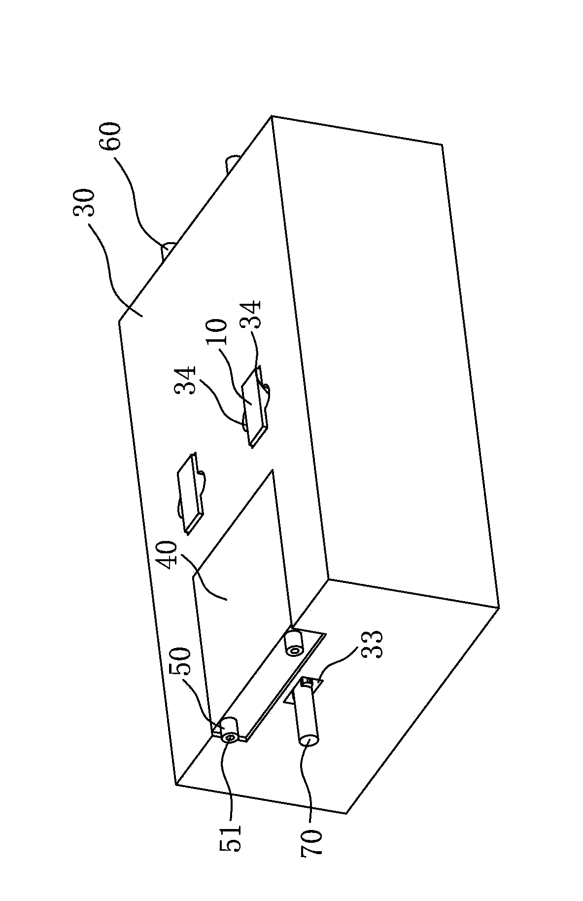
[0029] Please refer to Figure 2-Figure 5 , which are respectively shown as a three-dimensional structure schematic diagram of a preferred embodiment of the electronic component debugger of the present invention, a schematic diagram of an exploded structure of a preferred embodiment of the electronic component debugger of the present invention, and a schematic diagram of the electronic component of the present invention The schematic diagram of the back structure of a preferred embodiment of the device debugger is a schematic view of the use state of a preferred embodiment of the electronic component debugger of the present invention. in, Figure 2-Figure 4 Wires are not shown.
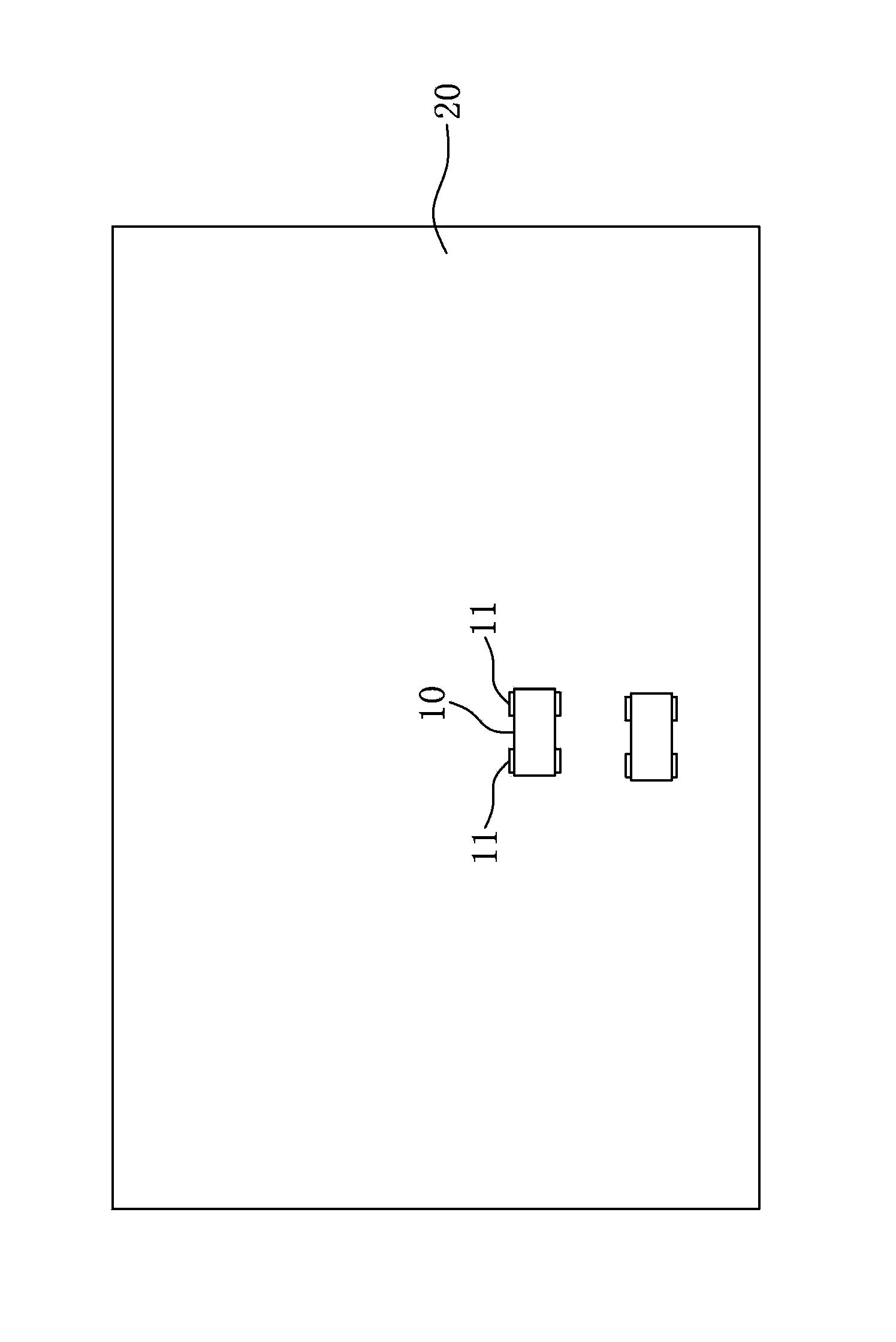
[0030] In order to achieve the above purpose, in the electronic component debugger provided by the present invention, the electronic component 10 (the electronic component can be a resistor, a capacitor, etc.) can be welded on the motherboard 20 through two welding points 11. For example, the debugg...
PUM
 Abstract
Description
Claims
Application Information