

Matrix type flexible switching charging stack
A matrix and flexible technology, applied in the field of charging piles, can solve the problems of charging pile transfer and cumbersome installation, prolong the installation period of charging piles, increase the difficulty of hoisting, etc., to ensure continuous extrusion effect, reduce installation costs, and reduce damage The effect of chance
- Summary
- Abstract
- Description
- Claims
- Application Information
AI Technical Summary
Problems solved by technology
Method used
Image

Examples
Embodiment 1
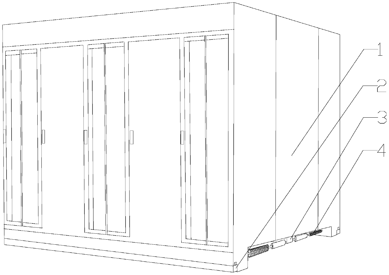
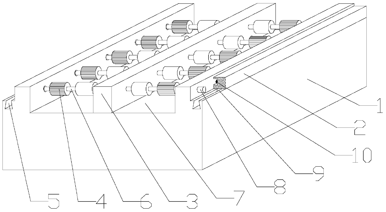
[0031] Such as Figure 1~6 As shown, this embodiment includes a body 1, a rectangular groove 7 with open ends is opened at the bottom of the body 1, and a support plate 3 is provided at the bottom of the rectangular groove 7, and a support plate 3 is provided on both sides of the rectangular groove 7, respectively. There are protruding strips parallel to the supporting plate 3, and a plurality of positioning holes are respectively arranged on the two side walls of the supporting plate 3, and fixing holes 16 corresponding to the positioning holes are respectively opened on the inner side walls of each protruding strip. Including a plurality of rotating shafts 6, a blind hole 14 communicating with the fixing hole 16 is opened on the outer wall of the protruding bar, one end of each of the rotating shafts 6 is placed in the fixing hole 16 and the other end is fixed in the blind hole 14, And the internal diameter of blind hole 14 is greater than the internal diameter of described ...
Embodiment 2
[0035] Such as Figure 2-4 As shown, this embodiment is based on Embodiment 1, the plane formed by the chute I 22 and the axis of the rotating shaft 6 is L, and the plane formed by the chute II 21 and the axis of the rotating shaft 6 is H, and an angle α is formed between L and H. The chute I22 and the chute II21 are not arranged on the same straight line, so that the connection points between the adjustment cylinder 13 and the rotating shaft 6 are at different positions on the outer peripheral wall of the rotating shaft 6, so that when the block I18 and the block II19 enter into the After the chute I22 and the chute II21, the connection between the adjustment cylinder 13 and the rotating shaft 6 is more stable. When the main body 1 is in the transmission process, when the stress damage occurs to the block I18 in the same adjustment cylinder 13, the block II19 can continue Keep the connection between the adjustment cylinder 13 and the rotating shaft 6, and because the block I...
Embodiment 3
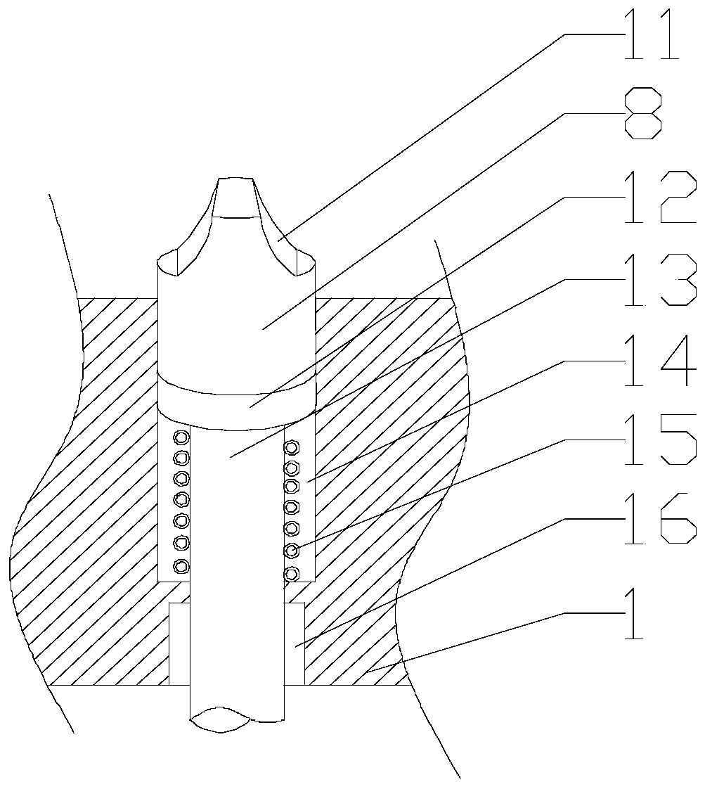
[0038] Such as image 3As shown, in this embodiment, two slopes 11 are provided on the outer end of the top column 8, and the two slopes 11 are symmetrically distributed along the axis of the top column 8, and the distance between each slope 11 and the axis of the top column 8 is An acute angle is formed, and when the slider 9 moves from the initial end of the dovetail groove 5 to its terminal end, the end surface of the limit rib 2 can press the top post 8 along any inclined surface 11 at the end of the top post 8 . Furthermore, the function of the limit flute 2 is to squeeze the outer ends of the plurality of top columns 8 to push the adjustment cylinder 13 to be connected with the rotating shaft 6 as a whole, and since the limit flute 2 is slidably set, the top Friction will be formed between the outer end surface of the column 8 and the inner side wall of the limit corrugated strip 2. For this, in order to reduce the wear between the two, the applicant has provided two slo...
PUM
 Abstract
Description
Claims
Application Information