
Eureka
For R&D, Eureka makes reading and utilizing patents & technical documents easy.
Eureka AIR
Designed for self-driven R&D workflows. Generate viable solutions, solve complex R&D challenges, empower your innovation with AI.

Eureka Materials
Designed for material experts only. Revolutionize your material R&D, from search, analyze, to developing new materials.

TechResearch
Generate reliable direction feasibility study reports for your R&D in just a few steps.

TechSeek
Discover and master advanced knowledge NOW. Basics, ideas, possibilities, all at once.

TechMind
As an expert in R&D Theories, TechMind can generates customized viable solutions instantly.

TechRisk
Analyze your overall solution with one click, know your potential R&D risks in advance.

TechMonitor
Get weekly tech updates, stay abreast of the latest tech innovations and key insights.
Progressive distributor for lubricant
A lubricant, progressive technology, applied in the field of progressive dispensers, can solve the problems of lubricant aging, hindered connection, lubrication system failure, etc., to achieve the effect of improving service life, improving accuracy, and improving transportation
- Summary
- Abstract
- Description
- Claims
- Application Information
AI Technical Summary
Problems solved by technology
Method used
Image

Examples
Embodiment Construction
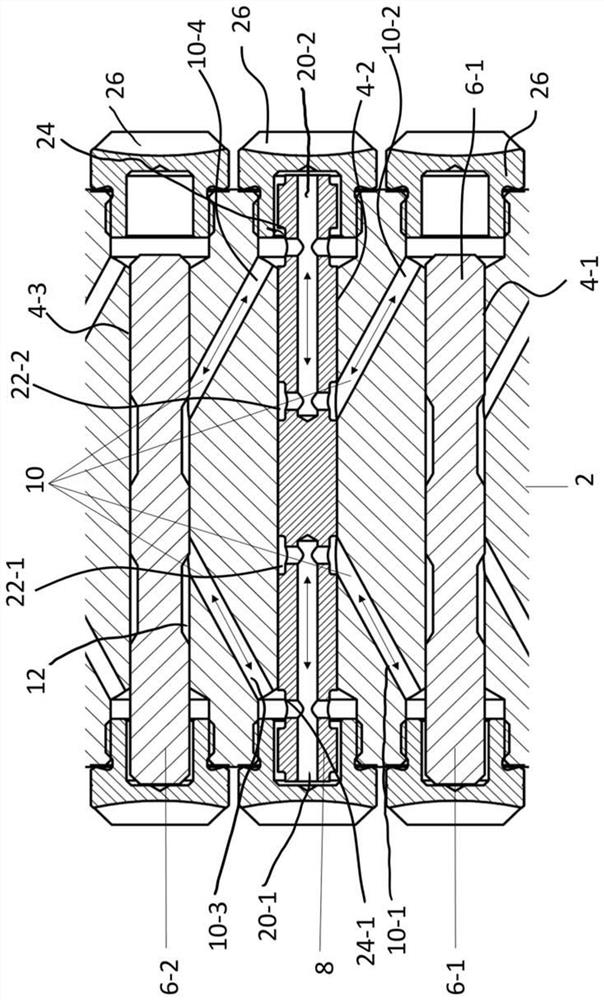
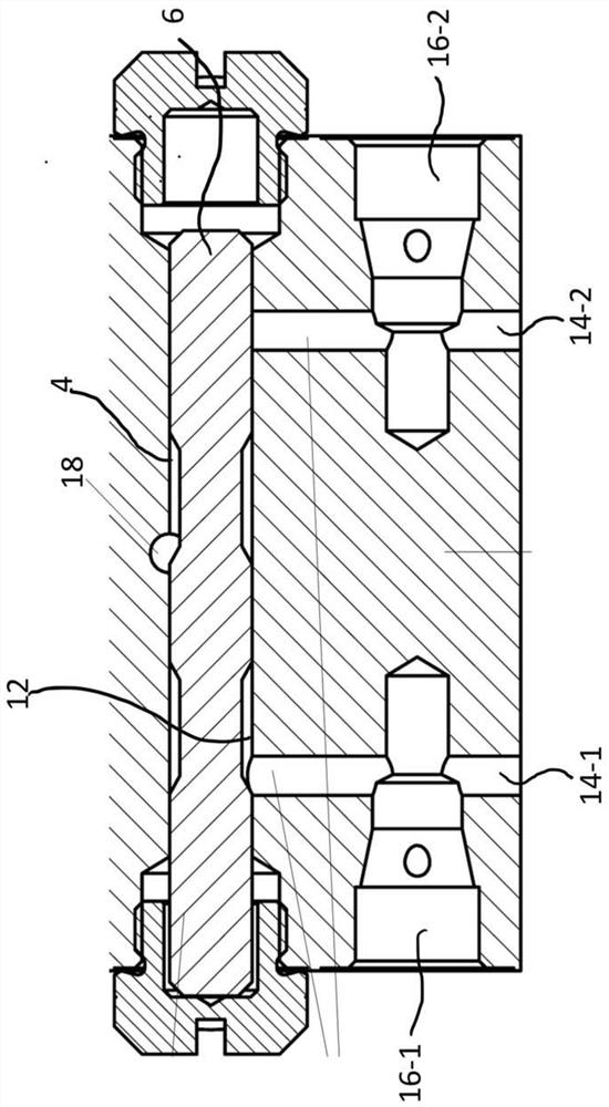
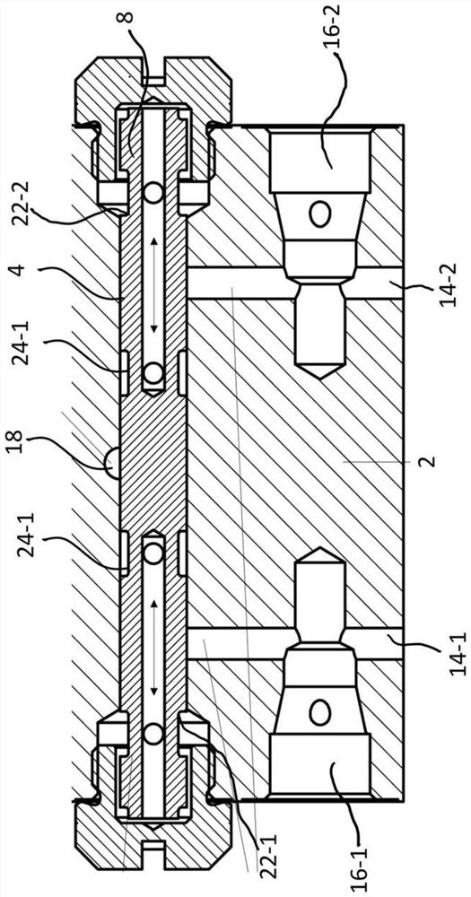
[0030] Figures 1 to 3 Various cross-sectional views through the components of the progressive dispenser 1 constructed in blocks are shown. To this end, the progressive distributor 1 generally comprises a housing block 2 into which a plurality of holes are introduced. From figure 1 , 2 3 and 3, it can be seen that the housing block 2 comprises a piston bore 4 in which a metering piston 6 or a balancing piston 8 can be accommodated.
[0031] From figure 1 It can also be seen that the piston bores 4 are connected to one another via connecting bores 10 . Lubricant passes from one piston bore 4 to the other piston bore 4 or lubricant outlet ( figure 1 not shown). exist figure 2 and 3The lubricant outlet hole 14 and the associated lubricant outlet 16 are shown in the sectional view of FIG. here, figure 2 is a sectional view through the lubricant outlet associated with the metering piston 6, while image 3 A sectional view through the lubricant outlet associated with th...
PUM
 Abstract
Description
Claims
Application Information
 - R&D Engineer
- R&D Manager
- IP Professional
- Industry Leading Data Capabilities
- Powerful AI technology
- Patent DNA Extraction
Browse by: Latest US Patents, China's latest patents, Technical Efficacy Thesaurus, Application Domain, Technology Topic, Popular Technical Reports.
© 2024 PatSnap. All rights reserved.Legal|Privacy policy|Modern Slavery Act Transparency Statement|Sitemap|About US| Contact US: help@patsnap.com