Crane and method for lifting main arm of crane

A crane and jib technology, applied in cranes and other directions, can solve the problems of main boom damage, aggravated jib deflection, crane overturning instability, etc., and achieve the effects of reducing deflection, reducing tipping moment, and reducing downward deflection.

Pending Publication Date: 2021-10-15
XCMG CONSTR MACHINERY
View PDF0 Cites 0 Cited by
  • Summary
  • Abstract
  • Description
  • Claims
  • Application Information

AI Technical Summary

Problems solved by technology

The increase of the jib will bring a greater overturning moment to the crane when the main arm is raised, which may cause the crane to overturn and become unstable
In addition, during the lifting process of the main arm of the crane, the main arm will be deflected under its own weight. With the lifting of the luffing system, after the arm head of the main arm is lifted from the ground, the main arm will be affected by the tension of the luffing system. Axial load will be generated, and this axial load will further aggravate the downdeflection of the boom, which may cause serious consequences of damage to the main boom
These phenomena restrict the increase of the main boom length of the crane

Method used


Image

  • Crane and method for lifting main arm of crane
  • Crane and method for lifting main arm of crane
  • Crane and method for lifting main arm of crane

Examples


Embodiment Construction

[0032] The following will clearly and completely describe the technical solutions in the embodiments of the present invention with reference to the accompanying drawings in the embodiments of the present invention. Obviously, the described embodiments are only some, not all, embodiments of the present invention. The following description of at least one exemplary embodiment is merely illustrative in nature and in no way taken as limiting the invention, its application or uses. Based on the embodiments of the present invention, all other embodiments obtained by persons of ordinary skill in the art without creative efforts fall within the protection scope of the present invention.

[0033] The relative arrangements of components and steps, numerical expressions and numerical values ​​set forth in these embodiments do not limit the scope of the present invention unless specifically stated otherwise. At the same time, it should be understood that, for the convenience of descriptio...


PUM


Abstract

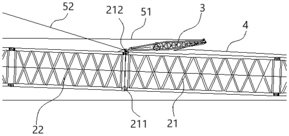
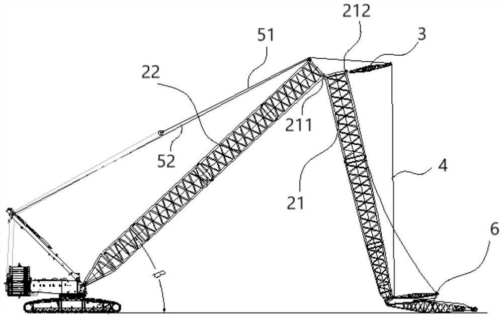
The invention discloses a crane and a method for lifting a main arm of the crane. The crane comprises a base, the main arm, a waist rope support, a traction piece, a first amplitude variation system and a second amplitude variation system, wherein the main arm comprises a first arm section and a second arm section, the second arm section is hinged to the base, a first connecting part and a second connecting part are arranged on the first arm section, the first arm section is hinged to the second arm section through the first connecting part, and the first arm section is detachably connected with the second arm section through the second connecting part; the waist rope support is of a rigid structure, and the first end of the waist rope support is connected with the first arm section; the traction piece is connected between the second end of the waist rope support and the first arm section; the first amplitude variation system comprises a telescopic first amplitude variation piece connected with the second end of the waist rope support; and the second amplitude variation system comprises a telescopic second amplitude variation piece connected with the second arm section. The crane has a small-amplitude working condition for enabling a cargo boom to be in a small amplitude and an arm lifting working condition for enabling the cargo boom to be lifted away from the ground; under the small-amplitude working condition, the second connecting part is connected with the second arm section so that the first arm section can be rigidly connected with the second arm section, the included angle between the first amplitude variation piece and the traction piece is smaller than 180 degrees, and the waist rope support is pressed through the resultant force of the acting force of the first amplitude variation piece and the traction piece on the waist rope support; and under the arm lifting working condition, the second connecting part is separated from the second arm section, so that the first arm section can rotate relative to the second arm section.

Description

technical field [0001] The invention relates to the field of lifting machinery, in particular to a crane and a method for lifting a main arm of the crane. Background technique [0002] Constant pursuit of working height is an inevitable trend in the development of cranes. In the prior art, the working height is usually increased by increasing the boom. Before operation, the main arm of the crane usually needs to be assembled on the ground, and then the main arm is raised to the working angle through its own luffing system. This working condition belongs to the non-working working condition of the crane, and the crane needs to complete this work before operation. After calculation and analysis, this working condition is generally a dangerous working condition of the luffing system and the stability of the whole machine, and it is also a dangerous working condition of the main arm. The increase of the jib will bring a larger tipping moment to the crane when the main boom is ...

Claims


Application Information

Patent Timeline
IPC IPC(8): B66C23/683B66C23/82
CPCB66C23/68B66C23/823B66C23/82
Inventor 赵江平周玉龙孟进军孙丽
Owner XCMG CONSTR MACHINERY
Why Eureka
Try Eureka