Steel structure supporting frame for constructional engineering
A technology of construction engineering and steel structure, which is applied in the field of support frames, can solve the problems of multi-part installation and fixation, and achieve the effects of increasing safety, convenient use, and increasing contact area
- Summary
- Abstract
- Description
- Claims
- Application Information
AI Technical Summary
Problems solved by technology
Method used
Image
Examples
Embodiment 1
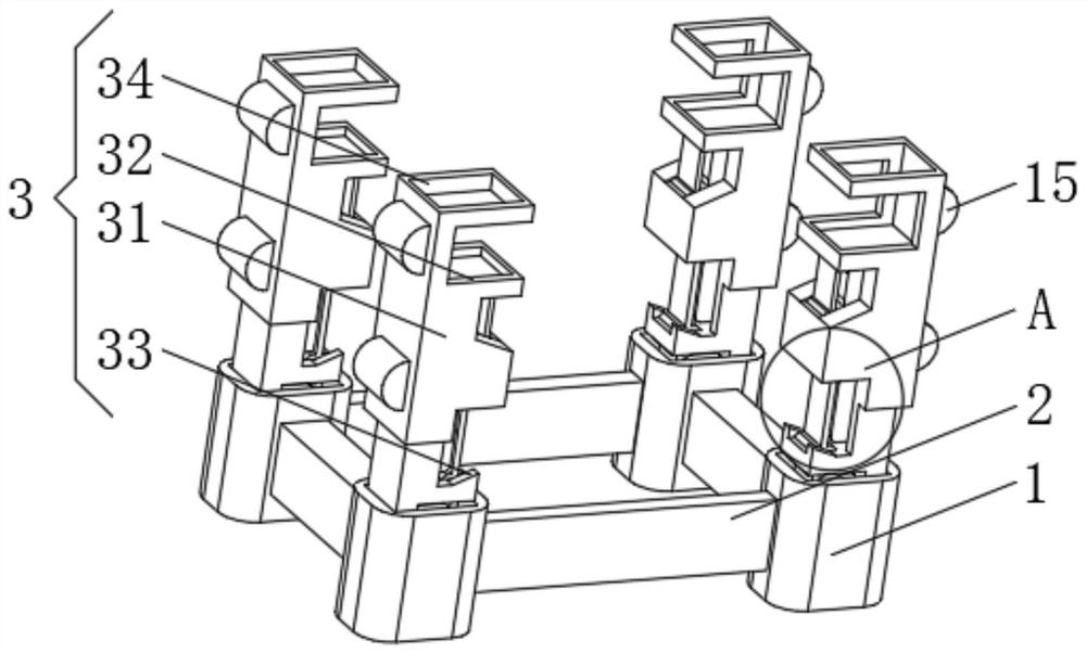
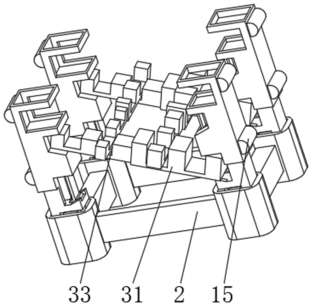
[0033] see Figure 1-3 , the present invention provides a technical solution: a steel structure support frame for construction engineering, including a base 1, a reinforcement plate 2 is fixedly connected between the bases 1, and the base 1 is provided with:
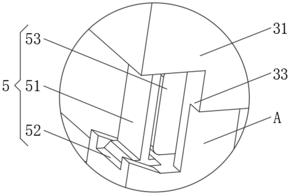
[0034] Splicing device 3, this splicing device 3 has a splicing rod 31, one side of the splicing rod 31 is symmetrically provided with an end draw-in groove 32 and an inner draw-in groove 33, the bottom of the inner draw-in groove 33 is designed to be inclined, and the splicing rod 31 includes a bottom at one end. The thin rod and the thick rod at one end of the top, the top of the splicing rod 31 is provided with a docking groove 34 .
[0035] One side of the splicing rod 31 is symmetrically provided with a guide protrusion 15 , and the cross section of the guide protrusion 15 is semicircular.
[0036] When in use, place the base 1 in a good position and weld and fix it with the reinforcing plate 2, install the splicin...
Embodiment 2
[0038] see Figure 1-5 , the present invention provides a technical solution: on the basis of Embodiment 1, a reinforcing device 4 is provided on the outside of the base 1, the reinforcing device 4 has a reinforcing plate 41, and one side of the base 1 is provided with a One side of the splicing rod 31 is rotatably connected with an outer pushing plate 43, and the end of the outer pushing plate 43 away from the splicing rod 31 is rotatably connected with the reinforcement plate 41. The top of the base 1 is provided with a lifting groove 44, and the lifting groove 44 The inner bottom is fixedly connected with a buffer spring 45 .
[0039] A rubber block 6 is installed on the side of the reinforcing plate 41 away from the base 1 , the rubber block 6 runs through the reinforcing plate 41 , and an anti-slip cone 7 is fixedly connected to the end of the rubber block 6 outside the reinforcing plate 41 .
[0040] A pressing groove 8 is provided on the side of the reinforcing plate 1...
Embodiment 3
[0044] see Figure 1-6 , the present invention provides a technical solution: on the basis of Embodiment 1, a protective device 5 is provided on the outside of the base 1, and the protective device 5 has a supporting steel plate 51; The fitted chute 52 and the interior of the internal card slot 33 are equipped with a buffer air bag 53 .
[0045] Both sides of the inner wall of the cushioning airbag 53 are fixedly connected with a mounting plate 10, one side of the mounting plate 10 is fixedly connected with an elastic plate 11, and the side of the elastic plate 11 away from the mounting plate 10 is fixedly connected with an impact plate 12, and the impact plate 12 consists of alternating connected hollow tubes.
[0046] The impact plate 12 is provided with a traction groove 13 on a side away from the elastic plate 11, and a magnet block 14 is installed inside the traction groove 13, and the material of the impact plate 12 is hard plastic.
[0047] When in use, the buffer air...
PUM
 Abstract
Description
Claims
Application Information
 - R&D
- Intellectual Property
- Life Sciences
- Materials
- Tech Scout
- Unparalleled Data Quality
- Higher Quality Content
- 60% Fewer Hallucinations
Browse by: Latest US Patents, China's latest patents, Technical Efficacy Thesaurus, Application Domain, Technology Topic, Popular Technical Reports.
© 2025 PatSnap. All rights reserved.Legal|Privacy policy|Modern Slavery Act Transparency Statement|Sitemap|About US| Contact US: help@patsnap.com


