A multiphase fluid temperature changing device

A temperature-changing device, multiphase fluid technology, applied in tubular elements, lighting and heating equipment, indirect heat exchangers, etc. The effect of high exchange efficiency

Active Publication Date: 2022-03-18
DONGFENG AUTOMOBILE COMPANY
View PDF0 Cites 0 Cited by
  • Summary
  • Abstract
  • Description
  • Claims
  • Application Information

AI Technical Summary

Problems solved by technology

[0003] The purpose of the present invention is to overcome the problem that the heat exchange device in the prior art cannot meet the simultaneous heat exchange of multiple fluids, and to provide a heat exchange device that can simultaneously perform heat exchange between multiple fluids, so that each fluid can reach more than the required temperature. phase fluid temperature change device

Method used


Image

  • A multiphase fluid temperature changing device
  • A multiphase fluid temperature changing device
  • A multiphase fluid temperature changing device

Examples


Embodiment 1

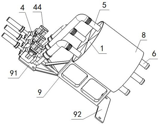
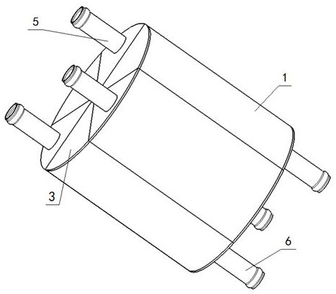
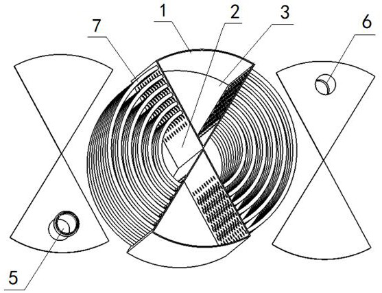
[0091] A multi-phase fluid temperature change device, the temperature change device includes a shell 1, a plurality of partitions 2 and heat exchange pipes 7, the shell 1 is a cylindrical structure, the partition 2 divides the internal space of the shell 1 Equally divided into an even number of fan-shaped sealing chambers 3, at least two heat exchange units are formed inside the temperature-changing device; the two opposite fan-shaped sealing chambers 3 are connected through multiple heat exchange pipes 7, and the two opposite fan-shaped sealing chambers The cavity 3 and the heat exchange pipe 7 connecting the two fan-shaped sealed chambers 3 form a heat exchange unit; the two ends of the heat exchange pipe 7 in the single heat exchange unit are fixedly connected with the partition plate 2 on the corresponding side, and the heat exchange The pipe 7 is located in the fan-shaped sealing cavity 3 between the two partitions 2 connected at its ends; the two opposite fan-shaped seali...

Embodiment 2

[0093] Embodiment 2 is basically the same as Embodiment 1, and its difference is:

[0094] The partition plate 2 divides the inner space of the housing 1 into six fan-shaped sealed cavities 3, and the six fan-shaped sealed cavities 3 include: a first-phase liquid inlet chamber 31, a second-phase liquid inlet chamber 32, and a three-phase liquid inlet chamber 33. One-phase liquid outlet chamber 34, two-phase liquid outlet chamber 35 and three-phase liquid outlet chamber 36; the electronic valve 4 includes: one-phase electronic valve 41, two-phase electronic valve 42 and three-phase electronic valve 43; The heat exchange pipe 7 includes: a one-phase heat exchange tube 71, a two-phase heat exchange tube 72 and a three-phase heat exchange tube 73; the heat exchange liquid inlet 5 includes: a one-phase heat exchange liquid inlet 51, a two-phase heat exchange Liquid inlet 52 and three-phase heat exchange liquid inlet 53; the heat exchange liquid outlet 6 includes: one-phase heat exc...

Embodiment 3

[0096] Embodiment 3 is basically the same as Embodiment 2, and its difference is:

[0097] The one-phase heat exchange tubes 71, two-phase heat exchange tubes 72, and three-phase heat exchange tubes 73 are arranged from top to bottom with one layer of one-phase heat exchange tubes 71, one layer of two-phase heat exchange tubes 72, and one layer of three-phase heat exchange tubes. The sequence of the heat pipes 73 is arranged circularly.


PUM


Abstract

A multi-phase fluid temperature-changing device, including a shell, a plurality of partitions and heat exchange pipes, the shell is a cylindrical structure, the partitions divide the inner space of the shell into an even number of fan-shaped sealed cavities, and the inside of the temperature-changing device is formed with At least two sets of heat exchange units; two opposite fan-shaped sealed chambers are connected through multiple heat exchange pipes, two opposite fan-shaped sealed chambers and heat exchange pipes connecting the two fan-shaped sealed chambers form a heat exchange unit ; Both ends of the heat exchange pipe in a single heat exchange unit are fixedly connected to the partitions on the corresponding side, and the heat exchange pipe is located in the fan-shaped sealed cavity between the two partitions connected at its ends; one in each heat exchange unit A heat exchange liquid inlet is provided on the top of the fan-shaped sealed chamber, and a heat exchange liquid outlet is provided at the bottom of the other fan-shaped sealed chamber in the heat exchange unit. In this design, by setting multiple heat exchange units, three or more fluids can exchange heat in one device at the same time, and the heat distribution is reasonable and the energy utilization rate is high.

Description

technical field [0001] The invention relates to a heat exchange device, in particular to a multiphase fluid temperature changing device, which is particularly suitable for heat exchange among various fluids. Background technique [0002] With the development of the automobile industry, automobile systems are becoming more and more complex, and the control requirements are becoming more and more refined. At present, most of the heat exchange devices on the market are single heat exchange between two fluids, but sometimes the heat exchange device not only needs to meet the heat exchange of two fluids, but may also exchange heat between three or more fluids at the same time. The multi-phase fluid temperature-changing device of the present invention, through a brand-new design, can satisfy the heat exchange of three or more fluids in one device at the same time, and through the precise control of the electronic valve, the various fluids can reach the required temperature, and th...

Claims


Application Information

Patent Timeline
Patent Type & Authority Patents(China)
IPC IPC(8): F28D7/00F28F27/02F28F9/007F28F9/00F28F1/00
CPCF28D7/0066F28F27/02F28F9/007F28F9/005F28F1/00
Inventor 刘中历徐远顾长志王金员程林汪斌王涛宋小伟李小娟曹春雨
Owner DONGFENG AUTOMOBILE COMPANY
Why Eureka
Try Eureka