Tubular heat exchanger with locating pin

A tubular heat exchanger and positioning pin technology, applied in the direction of heat exchanger type, heat exchanger shell, indirect heat exchanger, etc., can solve problems such as poor sealing effect, and achieve good recovery effect, good effect and efficiency high effect

Inactive Publication Date: 2015-02-11
SHANGHAI YUNLONG MACHINERY
View PDF1 Cites 0 Cited by
  • Summary
  • Abstract
  • Description
  • Claims
  • Application Information

AI Technical Summary

Problems solved by technology

[0003] The Chinese patent with the application number 201110050362.8 discloses a detachable tube-and-tube heat exchanger, which includes a shell, an upper tube sheet, a lower tube sheet, heat exchange tubes, and upper and lower tube sheets respectively installed on the upper and lower ends of the shell. A groove, and a sealing ring is set in the groove for connection. Although the above structure is easy to disassemble, the sealing effect is not good

Method used


Image

  • Tubular heat exchanger with locating pin

Examples


Embodiment

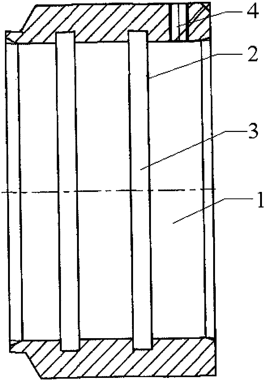
[0026] A tubular heat exchanger with positioning pins, a number of parallel tubes are arranged in the shell of the heat exchanger, the two ends of the tubes are fixedly connected with the head of the heat exchanger, a transverse baffle is set in the shell, and the columns A longitudinal baffle is set inside the tube, and the structure of the head 1 is as follows: figure 1 As shown, there are grooves 2 and positioning pins 4 for fixing the tubes and longitudinal baffles on the head 1. There are two grooves 2 and they are arranged in parallel. Rubber sealing ring 3. The positioning pin 4 is arranged on the side of the sealing head 1 . The transverse baffles arranged in the casing separate the tube arrays into heat exchange channels. In addition, fins may also be arranged in the heat exchange channel, and both sides of the fins are sealed by sealing strips. The fins that can be used are straight fins, porous fins, serrated fins and corrugated fins.

[0027] Said, parallel set...


PUM


Abstract

The invention relates to a tubular heat exchanger with locating pins. A plurality of tube nests are arranged inside the housing of the heat exchanger in parallel, the two ends of the tube nests are fixedly connected with end sockets of the heat exchanger, a transverse deflection baffle is arranged inside the housing, longitudinal baffle plates are arranged inside the tube nests, grooves and the locating pins for fixing the tube nests and the longitudinal baffle plates are arranged on the end sockets, and sealing rings used for sealing the tube nests are arranged inside the grooves. Compared with the prior art, the tubular heat exchanger provided by the invention has the advantages of good heat exchange effect, convenience in dismounting and the like.

Description

technical field [0001] The invention relates to a tubular heat exchanger, in particular to a tubular heat exchanger with positioning pins. Background technique [0002] Today's heat exchangers are simple in structure, light in weight, and low in cost. Under the same shell conditions, more heat transfer tubes can be arranged than other types of tube heat exchangers. However, the temperature difference of the fluid between the shell and the tube layer should not be too large, because when the temperature difference is too large, a large thermal stress will be generated, which will cause the joint between the tube and the tube sheet to loosen and cause leakage. In addition, because the tube sheet of this type of heat exchanger is fixed, it is difficult to overhaul, replace the tube or clean the shell. This heat exchanger is suitable for occasions where the shell-side medium is not easy to scale, or where there is scale but can be cleaned chemically; The case where the shell s...

Claims


Application Information

Patent Timeline
IPC IPC(8): F28D7/16F28F9/06
Inventor 王笑冰王智平
Owner SHANGHAI YUNLONG MACHINERY
Why Eureka
Try Eureka