Supercharge Your Innovation With Domain-Expert AI Agents!

Device and method for eliminating signal jitter measured by white light interferometer

A white light interferometer and signal measurement technology, which is applied in the field of optical measurement, can solve problems such as beat frequency jitter, optical delay line scanning non-uniform speed, etc., to achieve the effect of eliminating signal jitter and overcoming non-uniform scanning speed

Active Publication Date: 2022-05-10
武汉昊衡科技有限公司
View PDF16 Cites 0 Cited by
  • Summary
  • Abstract
  • Description
  • Claims
  • Application Information

AI Technical Summary

Problems solved by technology

[0004] The technical problem to be solved by the present invention is to propose a device and method for eliminating the signal jitter measured by the white light interferometer in view of the non-uniform scanning speed of the optical delay line in the current white light interferometer and the beat frequency jitter caused by the optical path jitter caused by mechanical friction.

Method used


Image

  • Device and method for eliminating signal jitter measured by white light interferometer
  • Device and method for eliminating signal jitter measured by white light interferometer
  • Device and method for eliminating signal jitter measured by white light interferometer

Examples


Embodiment 1

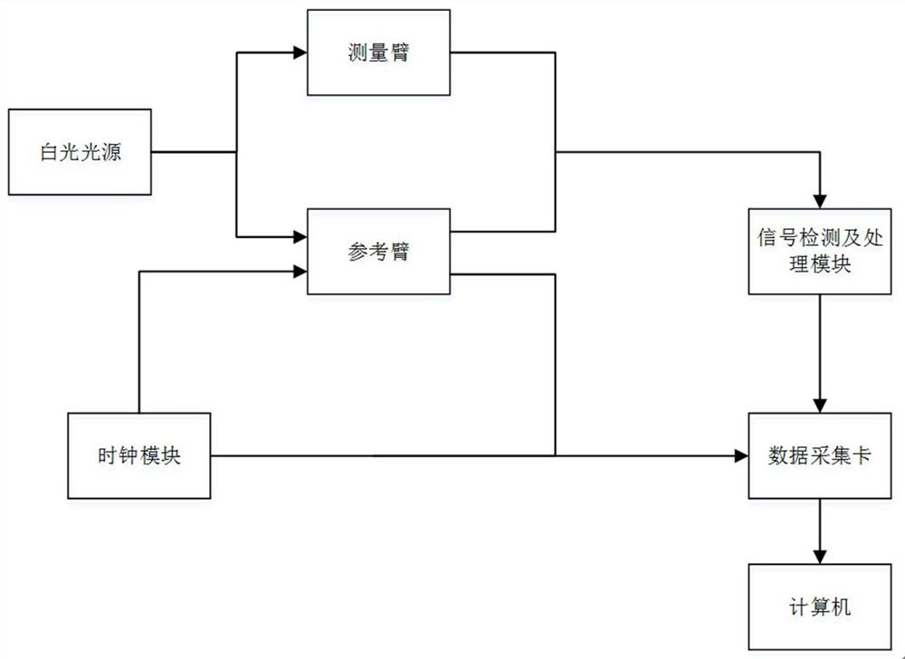
[0043] Such as figure 1 As shown, the embodiment of the present invention is used to eliminate the device for measuring signal jitter of white light interferometer including white light interferometer, clock module, signal detection and processing module, data acquisition card and computer, wherein white light interferometer includes white light source, measuring arm and reference arm.

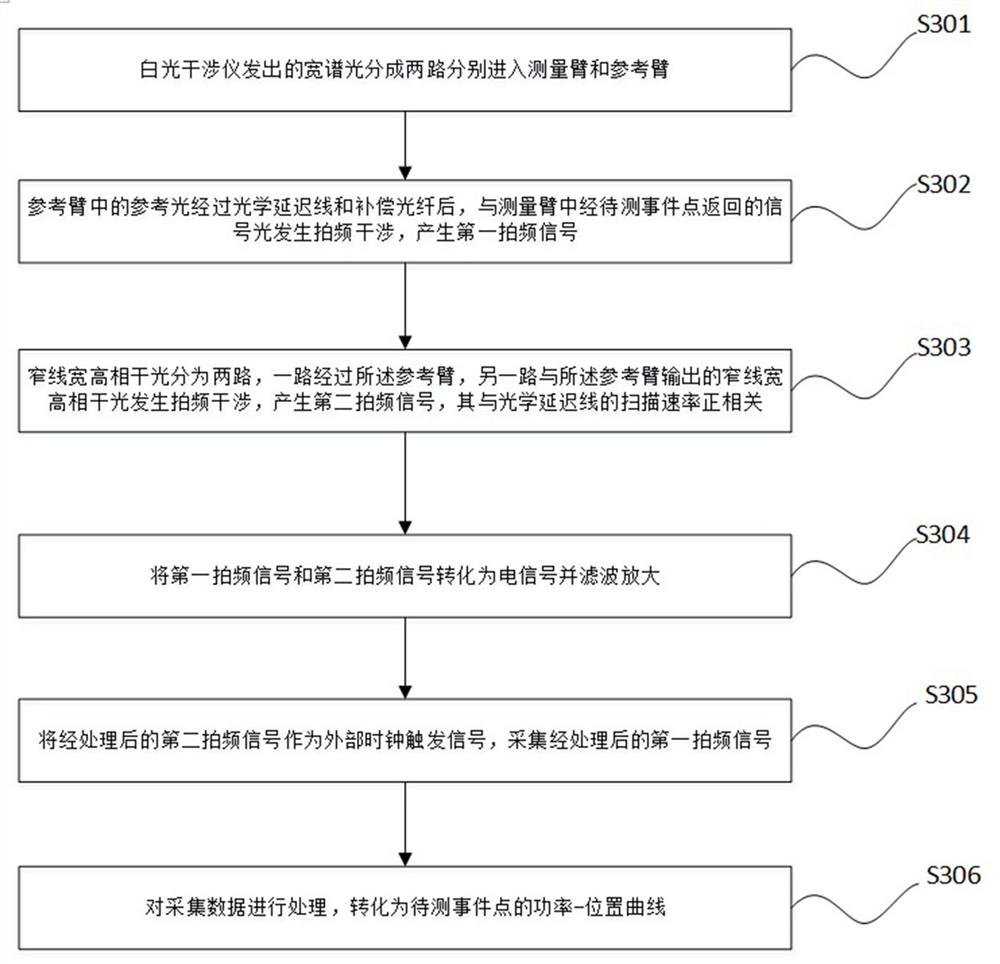
[0044] The white light source emits broad-spectrum light, which is divided into two paths and enters the measurement arm and the reference arm respectively;

[0045] The reference arm includes an optical delay line and a compensation fiber. The compensation fiber is used to adjust the arm length difference between the measurement arm and the reference arm. The reference light output by the reference arm interferes with the signal light returned by the event point to be measured in the measurement arm. The first beat frequency signal; the optical delay line can change the optical path of light...

Embodiment 2

[0062] In this example, if figure 2 As shown, the device for eliminating the signal jitter measured by the white light interferometer includes a white light interferometer 16 , a clock module 17 , a signal detection and processing module 13 , a data acquisition card 14 and a computer 15 .

[0063] The white light interferometer specifically includes a white light source 1, a first fiber coupler 2, a measurement arm, a reference arm and a second fiber coupler 5;

[0064] The measuring arm includes a fiber optic circulator 3 . The reference arm includes a first wavelength division multiplexer 8 , an optical delay line 9 , a compensation fiber 10 , and a second wavelength division multiplexer 11 .

[0065] The clock module 17 includes a narrow linewidth laser light source 6 , a reference arm (a reference arm shared with the white light interferometer) and a fourth fiber coupler 12 .

[0066] Specifically, the white light source 1 is connected to the input end of the first opti...


PUM


Abstract

The invention discloses a device and method for eliminating signal jitter measured by a white light interferometer. The method comprises steps: the wide-spectrum light emitted by the white light interferometer is divided into two paths and enters a measurement arm and a reference arm respectively; the reference light in the reference arm and the measurement arm Beat-frequency interference occurs in the signal light in the signal to generate the first beat-frequency signal; the narrow-linewidth high-coherence light is divided into two paths, one path passes through the reference arm, and the other path is generated by the narrow-linewidth high-coherence light output by the reference arm Beat frequency interference to generate a second beat frequency signal; use the processed second beat frequency signal as an external clock trigger signal to collect the processed first beat frequency signal; process the collected data and convert it into an event point to be measured power-position curve. The invention can eliminate the signal jitter produced by the inherent characteristics of the optical delay line in the measurement signal of the white light interferometer.

Description

technical field [0001] The invention relates to the field of optical measurement, in particular to a device and method for eliminating signal jitter measured by a white light interferometer. Background technique [0002] White light interferometer is an effective means and solution for measuring weak optical signals. Using the extremely short coherence length of white light, the detection and location of extremely weak signals can be realized. The white light interferometer usually uses an optical delay line to scan a certain distance, and observes the interference peak of the beat frequency spectrum to judge whether there is an event point, the position of the event point, and the echo power of the event point. [0003] However, due to the inherent characteristics of the optical delay line itself, its scanning speed cannot be maintained at a constant speed. If a fixed sampling rate is always used, then the distance scanned in the same period must be longer or shorter, whic...

Claims


Application Information

Patent Timeline
Patent Type & Authority Patents(China)
IPC IPC(8): G01D5/353
CPCG01D5/35306
Inventor 王辉文刘晓平张晓磊温永强叶阳
Owner 武汉昊衡科技有限公司
Features
  • R&D
  • Intellectual Property
  • Life Sciences
  • Materials
  • Tech Scout
  • Unparalleled Data Quality
  • Higher Quality Content
  • 60% Fewer Hallucinations
Learn More