Visual inspection system for tube-type bottle machine

A technology of machine vision inspection and visual inspection, which is applied in the direction of instruments, measuring devices, scientific instruments, etc., can solve the problems of high cost, inability to meet the comprehensive inspection of control bottles, and inability to detect appearance, etc., and achieve good detection results

Active Publication Date: 2021-10-15
湖北利康医用材料股份有限公司
View PDF3 Cites 0 Cited by
  • Summary
  • Abstract
  • Description
  • Claims
  • Application Information

AI Technical Summary

Problems solved by technology

[0002] The detection system of the control bottle machine usually uses laser detection to detect the outer diameter. Although the detection value is relatively accurate, it will be inaccurate when the tube is cut and the bad tube is discharged, and the interior of the laser detector is relatively complicated. When the instrument breaks down, it needs to be calibrated. The calibration can only be sent back to the original factory, and the laser detector can only detect the outer diameter, but cannot detect the appearance, such as gas lines, nodules, and retrograde lines. The existing technology exists The problem is that it is impossible to meet all-round detection of control bottles, and the cost of the detection machine is relatively high, so it is urgent to design a control bottle machine vision detection system to solve the above problems

Method used


Image

  • Visual inspection system for tube-type bottle machine
  • Visual inspection system for tube-type bottle machine
  • Visual inspection system for tube-type bottle machine

Examples


Embodiment Construction

[0022] The present invention will be described in further detail below in conjunction with the embodiments in the accompanying drawings, but this does not constitute any limitation to the present invention.

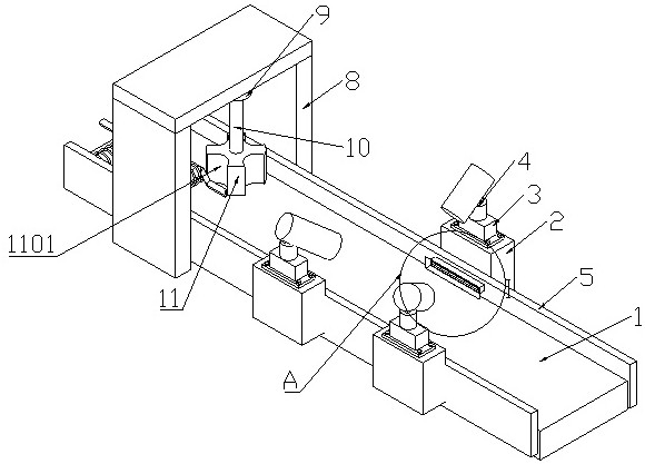
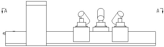
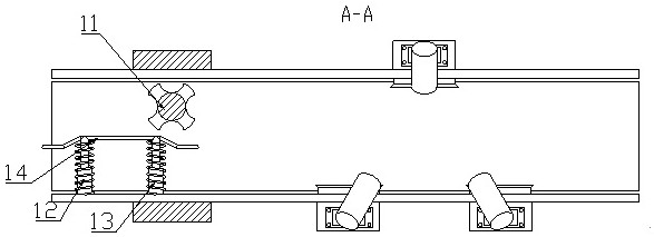
[0023] Such as Figure 1 to Figure 4 As shown, a control bottle machine vision inspection system provided by the present invention includes a conveyor belt 1, a visual detection component for inspecting the control bottle and a separation component for transporting the control bottle. 1 the baffles 5 on both sides, the fixing seat 2 arranged on the outer surface of the baffle 5, the supporting seat 3 arranged on the upper surface of the fixing seat 2 and the camera 4 arranged on the upper surface of the supporting seat 3, the said baffle 5 and the fixed The base 2 is fixedly connected, the fixed base 2 is fixedly connected with the support base 3 , and the camera 4 is fixedly connected with the support base 3 . By arranging the conveyor belt 1 , the fixing seat 2 , the s...


PUM


Abstract

The invention discloses a visual inspection system for a tube-type bottle machine, which comprises a conveying belt, a visual inspection component for inspecting tube-type bottles and a separation component for conveying the tube-type bottles, wherein the visual inspection component comprises baffles arranged on the two sides of the conveying belt, fixing bases arranged on the outer surfaces of the baffles, supporting bases arranged on the upper surfaces of the fixing bases and camera arranged on the upper surfaces of the supporting bases, the baffles are fixedly connected with the fixing bases, the fixing base is fixedly connected with the supporting base, the camera is fixedly connected with the supporting base, the number of the fixing bases, the supporting bases and the cameras is three, and the three fixing bases, the three supporting bases and the three cameras are distributed on the two sides of the conveying belt in a regular triangle shape. By arranging the fixing bases, the supporting bases, the cameras, the baffles, an illuminating lamp, a light shielding plate and the like, all-directional detection is performed on the tube-type bottle, the cost required by detection is reduced, and the detection efficiency is greatly improved.

Description

technical field [0001] The invention relates to the technical field of control bottle production, and more specifically relates to a machine vision inspection system for control bottles. Background technique [0002] The detection system of the control bottle machine usually uses laser detection to detect the outer diameter. Although the detection value is relatively accurate, it will be inaccurate when the tube is cut and the bad tube is discharged, and the interior of the laser detector is relatively complicated. When the instrument breaks down, it needs to be calibrated. The calibration can only be sent back to the original factory, and the laser detector can only detect the outer diameter, but cannot detect the appearance, such as gas lines, nodules, and retrograde lines. The existing technology exists The problem is that it is impossible to meet the all-round inspection of the control bottle, and the cost of the detection machine is relatively high, so it is urgent to d...

Claims


Application Information

Patent Timeline
Patent Type & Authority Applications(China)
IPC IPC(8): G01N21/892
CPCG01N21/892
Inventor 程健
Owner 湖北利康医用材料股份有限公司
Why Eureka
Try Eureka