Pile foundation grouting pressure testing device and method based on optical fiber sensing

A technology of grouting pressure and optical fiber sensing, which is applied in the test of foundation structure, foundation structure engineering, construction, etc., can solve the problem of outdated pile foundation grouting pressure test device, limitation of grouting technology popularization, and interference of empirical value, etc. problems, to achieve the effect of ensuring reliability, increasing the bonding range, and reducing the grouting time

Active Publication Date: 2021-10-19
江苏中云筑智慧运维研究院有限公司 +1
View PDF3 Cites 4 Cited by
  • Summary
  • Abstract
  • Description
  • Claims
  • Application Information

AI Technical Summary

Problems solved by technology

However, the accurate calculation of the grouting pressure at the grouting outlet at the pile end has not yet formed a unified standard. Real-time and dynamic monitoring of grouting pressure parameters during grouting construction is particularly important for controlling grouting effect
[0003] In the field of pile foundation grouting reinforcement under complex environmental conditions such as ultra-thick soft soil stratum and abundant groundwater, the grouting monitoring equipment and technology are still relatively backward. Currently, the grouting pressure is still monitored by the grouting pump pressure gauge and the records are read manually , there is no professional device for pile foundation grouting to monitor the grouting pressure. Human factors have a certain degree of interference to pile foundation grouting, which limits the promotion of post-grouting technology

Method used


Image

  • Pile foundation grouting pressure testing device and method based on optical fiber sensing
  • Pile foundation grouting pressure testing device and method based on optical fiber sensing
  • Pile foundation grouting pressure testing device and method based on optical fiber sensing

Examples


Embodiment Construction

[0038] The technical solution of the present invention will be further described below in conjunction with the accompanying drawings.

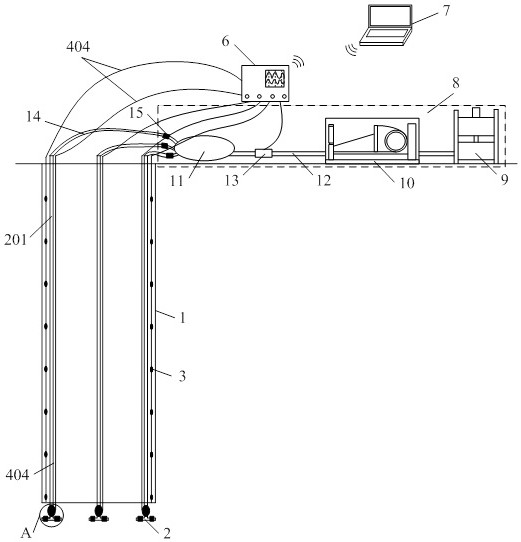
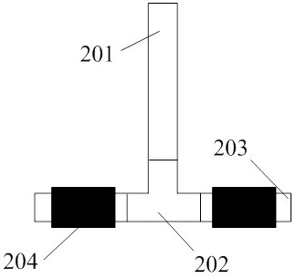
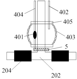
[0039] like figure 1As shown, a pile foundation grouting pressure test device and method based on optical fiber sensing in the present invention includes a steel cage 1, a pile end inverted T-shaped grouting device 2, an optical fiber strain sensor 3, a high-pressure elastic capsule, and a pressure test element 5 , data acquisition instrument 6, background processor 7 and grouting device 8. The inverted T-shaped grouting device 2 at the pile end is composed of a vertical grouting conduit 201, a tee joint 202 and a horizontal grouting device 203. The vertical grouting conduit 201 is connected to the grouting device by a distributor 11 through a grouting pipe 14. 8. The grouting device 8 includes a stirring slurry storage device 9, a grouting pump 10, a distributor 11, and a slurry delivery pipe 12. The slurry delivery pipe 12 is also provided ...


PUM


Abstract

The invention discloses a pile foundation grouting pressure testing device and method based on optical fiber sensing. The device comprises a reinforcement cage, a pile end inverted-T-shaped grouting device and a high-pressure elastic capsule with an optical fiber type pressure sensor, wherein the high-pressure elastic capsule is externally connected with an oil pump through a high-pressure oil pipe to be filled with high-pressure oil, the elastic capsule is completely expanded to be in effective contact with grout in the grouting process, the optical fiber type pressure sensor and a data acquisition instrument in the high-pressure elastic capsule are used for monitoring and storing the dynamic change of the oil pressure in the high-pressure elastic capsule in real time, and the dynamic change is transmitted to a background processor. The problems that the pile foundation grouting pressure is accurately determined and is interfered by human factors can be effectively solved, grouting pressure parameters can be adjusted through the obtained accurate grouting pressure, and the grouting reliability is guaranteed; and secondly, unified standard accumulation test data can be formed for accurate calculation of the grouting pressure of a pile end grout outlet, and a reference basis is provided for analyzing the upward-returning height of the pile end pressure grout.

Description

technical field [0001] The invention relates to the technical field of pile foundation grouting process, in particular to a pile foundation grouting pressure testing device based on optical fiber sensing and a working method thereof. Background technique [0002] Post-pile grouting technology is an engineering technology with strong practicability and a wide range of applications. It has been widely used in various fields such as underground buildings, bridges, subways, tunnels, transmission tower foundations, and offshore wind power. Improve the strength and stiffness of the soil, improve its stability and bearing capacity. At present, the domestic cast-in-situ piles adopt the post-grouting technology mainly to improve the defects of the construction process, increase the bearing capacity of the pile foundation, reduce the settlement, and then optimize the design of the pile length and save the project cost. Since the post-grouting project is a concealed project, its const...

Claims


Application Information

Patent Timeline
Patent Type & Authority Applications(China)
IPC IPC(8): E02D33/00E02D15/04
CPCE02D33/00E02D15/04E02D2250/0023E02D2600/10
Inventor 万志辉戴国亮胡涛钱晓楠高鲁超王志远
Owner 江苏中云筑智慧运维研究院有限公司
Why Eureka
Try Eureka