Material conveying and spraying device for 3D printing

A 3D printing and jetting device technology, applied in 3D object support structures, additive manufacturing, manufacturing tools, etc., can solve the problems of disjointed and inconvenient adjustment of advanced consumables, and achieve the adjustment of jetting position, avoid material breakage, and increase contact The effect of friction

Pending Publication Date: 2021-10-22
ANHUI CHUNGU 3D PRINTING INTELLIGENT EQUIP IND TECH RES INST CO LTD
View PDF3 Cites 0 Cited by
  • Summary
  • Abstract
  • Description
  • Claims
  • Application Information

AI Technical Summary

Problems solved by technology

[0004] This kind of device has the following disadvantages: when using, the output of the leading consumables is prone to

Method used


Image

  • Material conveying and spraying device for 3D printing
  • Material conveying and spraying device for 3D printing
  • Material conveying and spraying device for 3D printing

Examples


Embodiment 1

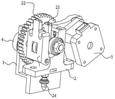
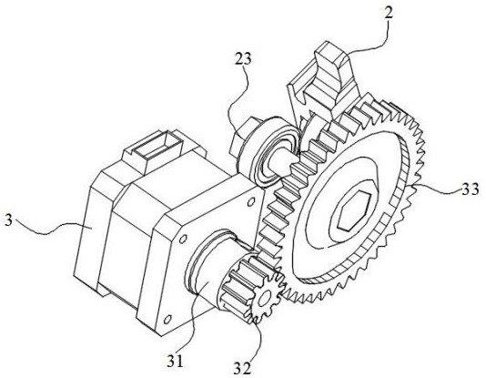
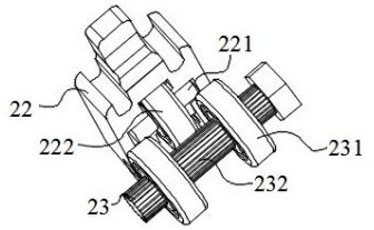
[0021] Embodiment 1: The present invention provides a material delivery and injection device for 3D printing, which includes an installation main frame 1 and a fixing frame 2 fixed at one end of the installation main frame 1, and one side of the installation main frame 1 is equipped with an installation and removal structure 4. A motor 3 is installed on one side of the installation main body frame 1, and a rotating shaft 31 is installed on the output end of the motor 3 through a coupling, and a driving gear 32 is fixed on the end of the rotating shaft 31 away from the motor 3, and the driving gear 32 is meshed with a driven gear 33, the center of the driven gear 33 is provided with a transmission shaft 23, both ends of the transmission shaft 23 are sleeved with a driving disc 231 in the axial direction, and one side of the fixed frame 2 A short guide tube 21 is fixed, and the bottom end of the fixed frame 2 is provided with a spray head 24; and one end of the motor 3 is install...

Embodiment 2

[0022] Embodiment 2: The present invention provides a material delivery and injection device for 3D printing, including an installation main frame 1 and a fixing frame 2 fixed at one end of the installation main frame 1, and an installation and disassembly structure is installed on one side of the installation main frame 1 4. A motor 3 is installed on one side of the installation main body frame 1, and a rotating shaft 31 is installed on the output end of the motor 3 through a coupling, and a driving gear 32 is fixed on the end of the rotating shaft 31 away from the motor 3, and the driving gear 32 is meshed with a driven gear 33, the center of the driven gear 33 is provided with a transmission shaft 23, both ends of the transmission shaft 23 are sleeved with a driving disc 231 in the axial direction, and one side of the fixed frame 2 A short guide tube 21 is fixed, and the bottom end of the fixed frame 2 is provided with a spray head 24; and one end of the motor 3 is installed...

Embodiment 3

[0023] Embodiment 3: The present invention provides a material delivery and injection device for 3D printing, including an installation main frame 1 and a fixing frame 2 fixed at one end of the installation main frame 1, and an installation and disassembly structure is installed on one side of the installation main frame 1 4. A motor 3 is installed on one side of the installation main body frame 1, and a rotating shaft 31 is installed on the output end of the motor 3 through a coupling, and a driving gear 32 is fixed on the end of the rotating shaft 31 away from the motor 3, and the driving gear 32 is meshed with a driven gear 33, the center of the driven gear 33 is provided with a transmission shaft 23, both ends of the transmission shaft 23 are sleeved with a driving disc 231 in the axial direction, and one side of the fixed frame 2 A short guide tube 21 is fixed, and the bottom end of the fixed frame 2 is provided with a spray head 24; and one end of the motor 3 is installed...


PUM


Abstract

The invention discloses a material conveying and spraying device for 3D printing. The material conveying and spraying device for 3D printing comprises a mounting main body frame and a fixing frame fixed to one end of the mounting main body frame, a mounting and dismounting structure is mounted on one side of the mounting main body frame, a motor is mounted on one side of the mounting main body frame, and a rotating shaft is mounted at the output end of the motor through a coupler. A driving gear is fixed to the end, away from the motor, of the rotating shaft, a driven gear is engaged with one side of the driving gear, a conveying shaft is arranged at the center position of the driven gear, the two ends of the conveying shaft are each sleeved with a driving disc in the axial direction, and a short guide cylinder is fixed to one side of the fixing frame. The side, away from the driving discs, of the conveying shaft is fixedly connected with one side of the mounting main body frame. According to the material conveying and spraying device for 3D printing, the mounting and dismounting structure is arranged on the mounting main body frame, the conveying shaft is arranged on the fixing frame, and a fixing disc is directly arranged on a positioning column on the surface of the printing device, so that the phenomena of material breakage and the like are avoided, and meanwhile the spraying position can be conveniently and randomly adjusted.

Description

technical field [0001] The invention relates to the field of 3D printing devices, in particular to a material injection device for 3D printing. Background technique [0002] With the development of society and the continuous progress of human beings, 3D printing is a kind of rapid prototyping technology, also known as additive manufacturing. It is based on digital model files and uses bondable materials such as powdered metal or plastic. The technology of constructing objects by layer-by-layer printing 3D printers uses nozzles to print, because some parts need to use more materials, and the injection volume of the nozzles is fixed, so the injection volume of the nozzles cannot be adjusted according to needs. , therefore, the application of the material injection device for 3D printing is more important. [0003] In China Patent Application Publication (Announcement) No.: CN212372713U discloses a 3D printing feeding injection device, which relates to the technical field of f...

Claims


Application Information

Patent Timeline
IPC IPC(8): B29C64/118B29C64/20B29C64/321B33Y30/00B33Y40/00
CPCB29C64/118B29C64/20B29C64/321B33Y30/00B33Y40/00
Inventor 李思文袁群桂东郭尚东周翔宗泽吕晨吴志华郑兰斌艾晓蕾唐思婷孙文明赵薇吴贫桂鑫张俐颖卞晨
Owner ANHUI CHUNGU 3D PRINTING INTELLIGENT EQUIP IND TECH RES INST CO LTD
Why Eureka
Try Eureka