Speed reduction device with adjustable height

A deceleration device and height technology, which is applied in the field of height-adjustable deceleration devices, can solve the problems that the height of the deceleration belt is not adjustable, it is difficult to adapt to different traffic conditions, etc., and achieves the effect of preventing potential safety hazards.

Pending Publication Date: 2021-10-22
HUAIYIN INSTITUTE OF TECHNOLOGY
View PDF4 Cites 0 Cited by
  • Summary
  • Abstract
  • Description
  • Claims
  • Application Information

AI Technical Summary

Problems solved by technology

[0005] Purpose of the invention: Aiming at the deficiencies in the prior art, the present invention provides a height-adjustable deceleration device, which adjusts the height of the deceleration device according to the frequency of use, so as to be suitable for different road traffic conditions and solve the problem of existing The height of the speed bump is not adjustable, making it difficult to adapt to different traffic conditions

Method used


Image

  • Speed reduction device with adjustable height
  • Speed reduction device with adjustable height
  • Speed reduction device with adjustable height

Examples


Embodiment Construction

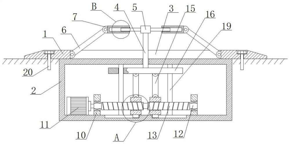
[0026] Such as Figure 1 to Figure 4 As shown, the height-adjustable deceleration device of the present invention is located in the installation groove on the ground. Components move.

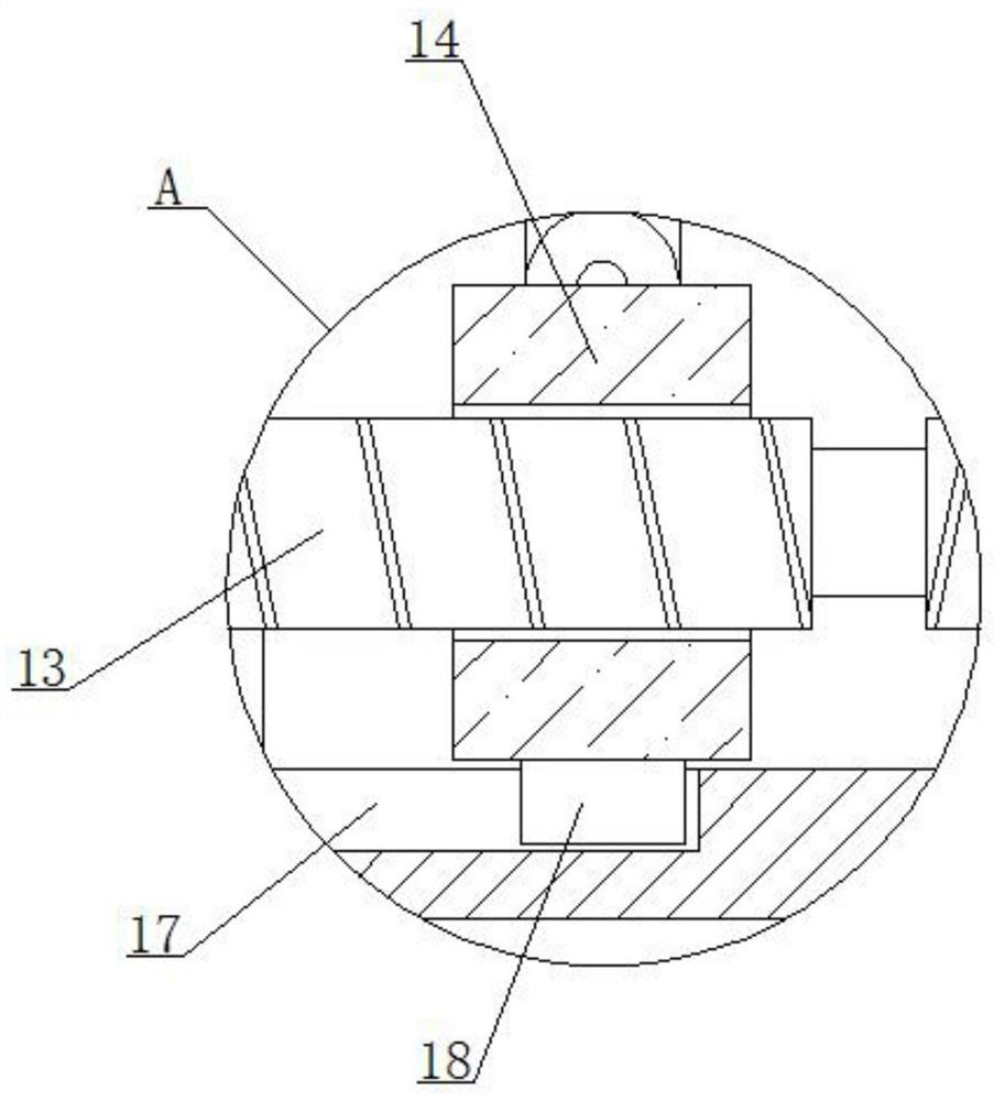
[0027] The adjustment assembly includes a motor 10, a rotating rod 12, two screw units that turn in opposite directions, a lifting plate 5, a connecting rod 15 and a connecting plate 16; the connecting rod 15 drives the connecting plate 16 and the lifting rod 4 to lift through the screw unit.

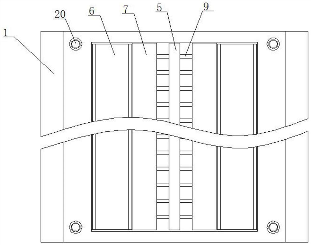
[0028] The bearing assembly includes an inclined plate 6 , a bearing plate 7 and a slide bar 9 , and the inclined plate 6 is connected with the slide bar 9 through the bearing plate 7 .

[0029] Both sides of the mounting plate 1 are inclined, and the fixed box 2 is located at the lower end of the mounting plate 1 . An opening 3 is provided on the mounting plate 1 , and several elevating rods 4 are connected in the fixed box 2 through an adjustment assembly. The elevating rods 4 pass through the fixed ...


PUM


Abstract

The invention discloses a speed reduction device with the adjustable height. The speed reduction device is located in a mounting groove in the ground. The speed reduction device comprises a fixing box, a lifting rod, an adjusting assembly and a bearing assembly. The adjusting assembly drives the bearing assembly to move through the lifting rod. The adjusting assembly comprises a motor, a rotating rod, a lifting plate, a connecting rod and a connecting plate; the rotating rod is sleeved with two screw units opposite in rotating direction, and the connecting rod drives the connecting plate and the lifting rod to ascend and descend through the screw units. The bearing assembly comprises an inclined plate, a bearing plate and a sliding rod, and the inclined plate is connected with the sliding rod through the bearing plate. A sliding rod groove is formed in the bearing plate, one end of the sliding rod is connected with the lifting plate, and the other end of the sliding rod moves in the sliding rod groove. According to the speed reduction device with the adjustable height, the height of the speed reduction device is adjusted by arranging the lifting rod, the adjusting assembly and the bearing assembly, so that the speed reduction device adapts to different road traffic conditions, and unnecessary potential safety hazards caused by too high vehicle speed are prevented.

Description

technical field [0001] The invention relates to a deceleration device, in particular to a height-adjustable deceleration device. Background technique [0002] At present, the increase in traffic flow has led to frequent traffic accidents on the other hand. Speeding is the main cause of traffic accidents. In order to control the speed of vehicles at some intersections with large traffic volumes, road deceleration belts have emerged as the times require. The speed bump is a traffic facility installed on the road to slow down the passing vehicles. The material is usually rubber, and some speed bumps are made of iron. The speed bump controls the speed of the vehicle in a mandatory and warning manner, thereby reducing traffic accidents. [0003] The driver's discomfort when driving the vehicle through the deceleration device is the key point for him to effectively control the vehicle speed. The stronger the discomfort, the stronger the driver's desire to decelerate. [0004] H...

Claims


Application Information

Patent Timeline
Patent Type & Authority Applications(China)
IPC IPC(8): E01F9/529
CPCE01F9/529
Inventor 段国宇吴鼎新蔡彦琦黄万仙杨家恒符政
Owner HUAIYIN INSTITUTE OF TECHNOLOGY
Why Eureka
Try Eureka