Structure of anti-blocking drainage facility of retaining wall

A technology for drainage facilities and retaining walls, applied in underwater structures, soil protection, infrastructure engineering, etc., can solve the problems of consuming a lot of manpower and material resources, loss of drainage function, difficult disassembly and cleaning, etc., so as to be widely popularized and used , high practical value and low maintenance cost

Pending Publication Date: 2021-10-22
STATE GRID FUJIAN ELECTRIC POWER RES INST +1
View PDF7 Cites 1 Cited by
  • Summary
  • Abstract
  • Description
  • Claims
  • Application Information

AI Technical Summary

Problems solved by technology

[0003] The drainage of the existing retaining wall adopts a reverse filter bag or filter layer behind the drainage pipe. With the increase of time, the natural settlement and consolidation of the cohesive soil will form an impermeable layer with the reverse filter layer and filter bag, which will cause blockage. The drainage pipe makes it lose its drainage function. At the same time, it is difficult to disassemble and clean the existing retaining wall drainage structure after construction. Once the drainage pipe is blocked, it will take a lot of manpower and material resources to clear it. , the cleaning cost is high, so we improve this and propose a structure of retaining wall anti-clogging drainage facilities

Method used


Image

  • Structure of anti-blocking drainage facility of retaining wall
  • Structure of anti-blocking drainage facility of retaining wall
  • Structure of anti-blocking drainage facility of retaining wall

Examples


Embodiment

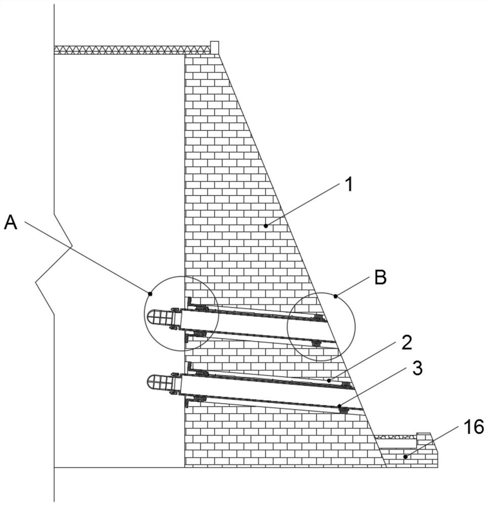
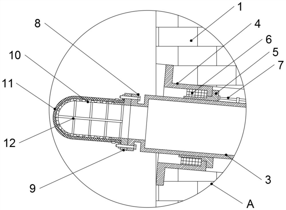
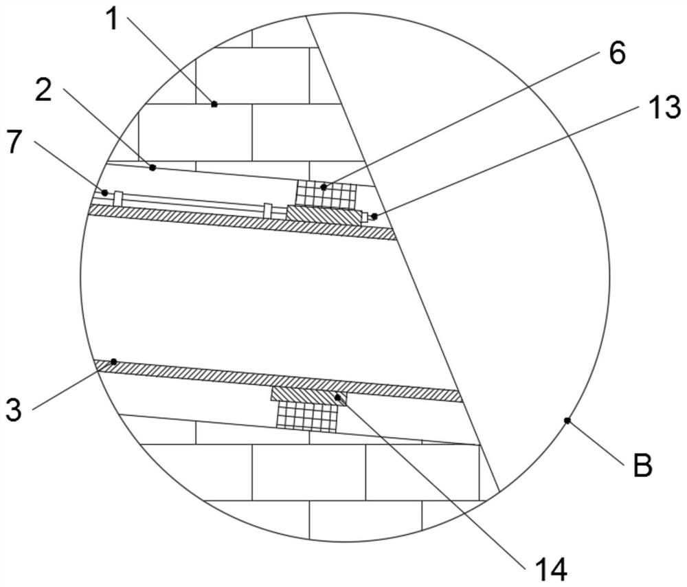
[0022] Example: such as Figure 1-4 As shown, the structure of a retaining wall anti-clogging drainage facility of the present invention includes a retaining wall 1, and the retaining wall 1 is provided with several groups of downwardly inclined drainage holes 2, and the two ends of the drainage holes 2 Respectively communicate with the outer surface of the retaining wall 1, the end of the drain hole 2 near the retaining side of the retaining wall 1 is fixedly connected with the limit seat 4, and the inside of the drain hole 2 is equipped with a drain pipe 3. The drain pipe 3 is fixedly fitted with a limiting ring 5 at one end close to the limiting seat 4, and is fitted with a mounting ring 14 at an end away from the limiting ring 5, and the outer sides of the limiting ring 5 and the mounting ring 14 are both The fixed sleeve is equipped with an inflatable ring 6, and the drain pipe 3 is provided with a connecting flange 8 at one end close to the retaining side of the retainin...


PUM


Abstract

The invention discloses a structure of an anti-blocking drainage facility of a retaining wall. The structure comprises a retaining wall body, wherein a plurality of groups of drainage holes which are inclined downwards are formed in the retaining wall body; one end, close to one side of the retaining wall body, of each drainage hole is fixedly connected with a limiting base; a drainage tube is mounted inside each drainage hole; one end, close to the limiting base, of each drainage tube is fixedly equipped with a limiting ring in a sleeving mode; one end, away from the limiting ring, of each drainage tube is equipped with a mounting ring in the sleeving mode; the outer sides of the limiting rings and the mounting rings are fixedly equipped with gas-filling rings in the sleeving mode; one end, close to one side of the retaining wall body, of each drainage tube is equipped with a connecting flange; one side of each connecting flange is connected with a connecting ring; one side of each connecting ring is fixedly connected with a supporting net; and the outer side of each supporting net is equipped with a permeation filter screen in the sleeving mode. The anti-blocking drainage structure of the retaining wall is simple and reasonable in structure, is novel in design, is good in anti-blocking effect, is simple and convenient to dismount, is relatively low in maintenance cost, has a relatively high practical value, and is convenient for being widely popularized and used.

Description

technical field [0001] The invention relates to a drainage structure, in particular to a structure of an anti-clogging drainage facility for a retaining wall. Background technique [0002] The retaining wall refers to the structure that supports the filling soil of the roadbed or the soil mass of the hillside, and prevents the deformation and instability of the filling soil or soil mass. The water behind the wall forms hydrostatic pressure, reduces the frost heave pressure of the backfill soil in cold areas, and eliminates the expansion pressure of the cohesive soil filling after being soaked in water. [0003] The drainage of the existing retaining wall adopts a reverse filter bag or filter layer behind the drainage pipe. With the increase of time, the natural settlement and consolidation of the cohesive soil will form an impermeable layer with the reverse filter layer and filter bag, which will cause blockage. The drainage pipe makes it lose its drainage function. At the ...

Claims


Application Information

Patent Timeline
Patent Type & Authority Applications(China)
IPC IPC(8): E02D3/10E02D29/02
CPCE02D3/10E02D29/02
Inventor 李熙江世雄陈垚王重卿陈泽钦车艳红翁孙贤程慧青陈震平
Owner STATE GRID FUJIAN ELECTRIC POWER RES INST
Why Eureka
Try Eureka